Al technical title is built by PatSnap Al team. It summarizes the technical point description of the patent document.
A production process and technology of disc brakes, applied in the field of production process of pumps on disc brakes, can solve the problems of labor costs, high plant costs, many operators, high R&D costs, etc., and achieve simple and efficient processing, high product qualification rate, and improved The effect of artificial potency
Inactive Publication Date: 2019-02-19
RUIAN JINJI VEHICLE PARTS COMPONENTS
View PDF6 Cites 1 Cited by
Summary
Abstract
Description
Claims
Application Information
AI Technical Summary
This helps you quickly interpret patents by identifying the three key elements:
Problems solved by technology
Method used
Benefits of technology
Problems solved by technology
However, the traditional mechanical processing equipment requires at least 2 CNC machines, 3 milling machines, 1 ordinary bench drill, 1 special bench drill, 5 three-station bench drills, a total of 12 machine tools; each process is operated separately, and materials are stacked on site More materials are discharged slowly. If you want to operate continuously, the relationship between semi-finished products and finished products is generally more than 10:1; the production cycle of the machine is unbalanced, the error is large, the scrap rate is high, and there are many operators, and the machine occupies a large area and the labor cost , High plant cost
[0003] Furthermore, there is a one-to-one connection between the existing oil cup and the disc brake upper pump, that is, one type of brake upper pump can only be installed with the corresponding type of oil cup, and the model of the brake upper pump or oil cup cannot be replaced at will. , or the brake upper pump and the oil cup are integrally formed, but this setting is not only unsightly in appearance but also difficult to maintain and replace, and the structure of one-to-one connection has resulted in the development of new oil cups or new disc brake upper pumps. It is necessary to re-open the mold to adapt to the original structure for connection. The cost of each mold opening is about 20,000 yuan, resulting in high R&D costs and time-consuming and laborious
Method used
Image
Click on the blue label to locate the original text in one second.
Reading with bidirectional positioning of images and text.
Examples
Embodiment Construction
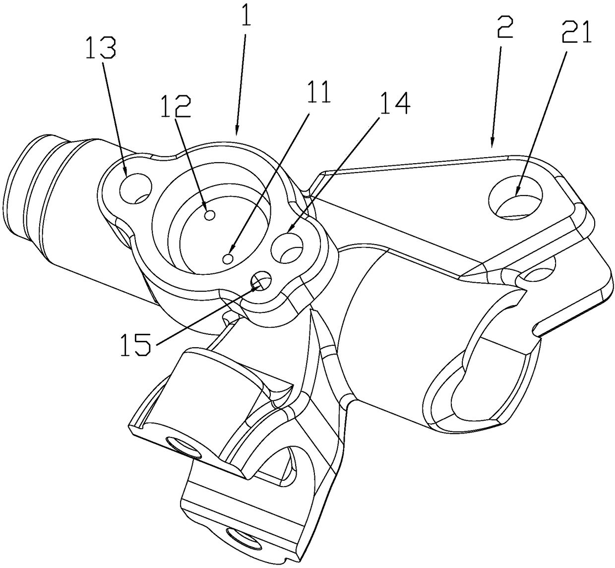
[0021] See figure 1 Shown: A manufacturing process of a disc brake upper pump, which is characterized by including the following steps:
[0022] Step 1: Die-casting the raw materials into a disc brake upper pump blank part, the upper pump blank part includes an oil cup connecting end 1 for connecting an oil cup 1 and a handle connecting end 2 for connecting a brake handle;
[0023] Step 2: Cut off the leftover material of the pump blank on the disc brake and remove the burrs;
[0024] Step 3: Put the rough parts of the disc brake on the pump for sand throwing;
[0025] Step 4: Perform mechanical processing on the upper pump rough parts of the disc brake after sanding, and the mechanical processing includes the following steps:
[0026] a) Use CNC machine tools to drill the plunger hole;
[0027] b) Using the plunger hole as the positioning hole, use the first drilling rig to drill the oil supply hole 11 and the oil return hole 12 in the oil cup connecting end 1;
[0028] c) Use the first...
PUM
Abstract
The invention relates to a manufacturing process of a disc brake upper pump. The manufacturing process is characterized by comprising the following steps that 1, mold-casting is carried out on a raw material to prepare a disc brake upper pump blank piece, the upper pump blank piece comprises an oil cup connecting end used for being connected with an oil cup, and a handle connecting end used for being connected with a brake handle; 2, a leftover material of the disc brake upper pump blank piece is cut off and burrs are removed; 3, sand blasting treatment is carried out on the disc brake upper pump blank piece; 4, mechanical machining is carried out on the disc brake upper pump blank piece which is subjected to the sand blasting treatment; 5, coating treatment is carried out on the disc brake upper pump blank piece which is machined through the step four so as to obtain a disc brake upper pump finished product piece; and 6, assembling is carried out on the coated disc brake upper pump finished product piece.
Description
Technical field [0001] The invention relates to the field of motorcycle disc brake upper pumps, in particular to a manufacturing process of disc brake upper pumps. Background technique [0002] In the prior art, the traditional manufacturing process of a disc brake upper pump generally includes the following steps: gravity casting, material cutting, burring, T6 heat treatment, sand throwing, mechanical processing, painting, and assembly. The mechanical processing includes the following steps: turning holes, drilling plunger holes (gun drill or drilling + stranding), milling handle grooves (including straight grooves), drilling oil supply holes and oil return holes, drilling handle holes, drilling half-cover holes , Drilling oil cup hole, drilling switch hole, milling oil cup surface, drilling side mirror, drilling oil hole, burr packing. However, the traditional mechanical processing equipment requires at least 2 CNC machines, 3 milling machines, 1 ordinary bench drill, 1 specia...
Claims
Application Information
Patent Timeline
Application Date:The date an application was filed.
Publication Date:The date a patent or application was officially published.
First Publication Date:The earliest publication date of a patent with the same application number.
Issue Date:Publication date of the patent grant document.
PCT Entry Date:The Entry date of PCT National Phase.
Estimated Expiry Date:The statutory expiry date of a patent right according to the Patent Law, and it is the longest term of protection that the patent right can achieve without the termination of the patent right due to other reasons(Term extension factor has been taken into account ).
Invalid Date:Actual expiry date is based on effective date or publication date of legal transaction data of invalid patent.