Tank reactor for producing surfactants, and application method thereof

A kettle-type reactor and surfactant technology, applied in the field of kettle-type gas-phase sulfonation reaction equipment, can solve problems such as reducing the viscosity of raw materials, difficulty in tail gas treatment, and loss of raw materials, so as to improve selectivity and avoid over-sulfonation Effect

Pending Publication Date: 2019-02-19
SHANDONG DAMING FINE CHEM CO LTD
View PDF14 Cites 0 Cited by
  • Summary
  • Abstract
  • Description
  • Claims
  • Application Information

AI Technical Summary

Problems solved by technology

[0003] Gas-phase membrane reactor is currently the most widely used sulfonation reactor, which is very mature for the production of dodecylbenzenesulfonic acid, heavy alkylbenzenesulfonic acid, etc. When sulfonating raw materials such as residual oil, there are the following disadvantages: (1) Heavy components such as colloids and asphaltenes in the raw materials are easily over-sulfonated during the sulfonation process, thereby coking and easily clogging the reactor; (2) due to the use of A large amount of air to SO 3 Therefore, for raw materials with high viscosity, the method of adding an inert solvent cannot be used to reduce the viscosity of the raw materials. The only way to increase the reaction temperature is to make the raw materials naturally cast on the inner wall of the reactor to form a film. Due to the high reaction temperature, it is easy to cause Over-sulfonation of raw materials, resulting in loss of raw materials and decline in product quality; (3) A large amount of tail gas is generated during the sulfonation process, which contains a large amount of sulfur dioxide, and the tail gas treatment is difficult

Method used


Image

  • Tank reactor for producing surfactants, and application method thereof

Examples


Embodiment 1

[0030] Embodiment 1 A kind of tank reactor for producing surfactant

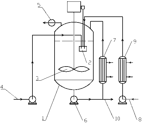
[0031] Such as figure 1 In the shown embodiment, a kind of tank reactor that is used to produce surfactant comprises buffer tank 1, the gas-liquid mixer 2 that is arranged in buffer tank 1, the agitator 3 that is arranged in buffer tank 1, and The diluted raw oil inlet 4 connected to the gas-liquid mixer 2 in the buffer tank 1, the vacuum pump 5 connected to the buffer tank 1, the circulation discharge system arranged outside the buffer tank 1 and the diluted sulfur trioxide arranged outside the buffer tank 1 Feeding system; the circulating discharge system includes a circulating discharge pump 6 and a heat exchanger 7, one end of the circulating discharging pump 6 communicates with the bottom of the buffer tank 1, and the other end of the circulating discharging pump 6 communicates with one end of the heat exchanger 7 , the other end of the heat exchanger 7 communicates with the buffer tank 1 top; the circ...

Embodiment 2

[0034] Embodiment 2 A kind of use method for the tank reactor of producing surfactant

[0035] The using method of the present embodiment is based on a kind of tank reactor for producing surfactant in embodiment 1, specifically comprises the steps:

[0036] (1) Separately dilute the raw material oil and sulfur trioxide: subtract the fourth-line raw material oil, the boiling range is 450-500°C, dilute according to the weight ratio of raw material oil: dichloromethane = 1:1.5, SO 3 Dilute with dichloromethane at a weight ratio of 1:2;

[0037] (2) Add 1000Kg of diluted raw oil into the buffer tank 1;

[0038] (3) Turn on the agitator 3, turn on the cold water jacket of the buffer tank 1, wait until the temperature in the buffer tank 1 drops to 10°C, turn on the vacuum pump 5 to evacuate, and maintain the negative pressure in the buffer tank 1 at 2mmHg;

[0039] (4) Start the gas-liquid mixer 2 in the buffer tank 1;

[0040] (5) The temperature of the evaporator 9 is 30°C, sta...

Embodiment 3

[0043] Embodiment 3 A kind of use method for the tank reactor of producing surfactant

[0044] The using method of the present embodiment is based on a kind of tank reactor for producing surfactant in embodiment 1, specifically comprises the steps:

[0045](1) Separately dilute raw oil and sulfur trioxide: mix vacuum residue, diesel oil, and dichloromethane at a weight ratio of 1:0.5:3 to prepare diluted oil, and sulfur trioxide and dichloromethane at a ratio of 1:2 The weight ratio is diluted;

[0046] (2) Add 1000Kg of diluted raw material oil into the buffer tank 1;

[0047] (3) Turn on the agitator 3, turn on the cold water jacket of the buffer tank 1, wait until the temperature in the buffer tank 1 drops to 10°C, turn on the vacuum pump 5 to evacuate, and maintain the negative pressure in the buffer tank 1 at 2mmHg;

[0048] (4) Start the gas-liquid mixer 2 in the buffer tank 1;

[0049] (5) The temperature of the evaporator 9 is 30°C, start to pump diluted SO into the...


PUM


Abstract

The invention relates to the technical field of tank-type gas phase sulfonation reaction devices for surfactants for tertiary oil recovery, in particular to a tank reactor for producing the surfactants, and an application method thereof. The tank reactor comprises a buffer tank, a gas-liquid mixer arranged in the buffer tank, a stirrer arranged in the buffer tank, a diluted raw oil inlet communicated with the gas-liquid mixer in the buffer tank, a vacuum pump communicated with the buffer tank, a circulating discharge system arranged outside the buffer tank, and a diluted sulfur trioxide feeding system arranged outside the buffer tank. The tank reactor and the application method thereof have the advantages that the applicable reaction temperature of the reactor ranges from -20 DEG C to 40 DEG C, the sulfonation reaction depth of complex raw materials can be controlled under low temperature conditions, materials difficult to react can be sulfonated under high temperature conditions, andthe tank reactor is particularly suitable for production of the surfactants for the tertiary oil recovery from the low-cost and complexly-composed raw materials.

Description

technical field [0001] The invention relates to the technical field of tank-type gas-phase sulfonation reaction equipment for surfactants used in tertiary oil recovery, in particular to a tank-type reactor for producing surfactants and a use method thereof. Background technique [0002] Sulfonate surfactants are the largest and most widely used category of anionic surfactants, and they are also developed earlier and have more varieties. Sulfonate surfactants are commonly used surfactants in tertiary oil recovery, and are widely used in major oilfields in China due to their low price and good oil displacement effects. However, the raw materials used in the production of surfactants have the characteristics of high viscosity, complex components, and large differences between different batches of raw materials. Therefore, a special reactor is needed for sulfonation in order to ensure the smooth progress of the reaction and the quality of the product. [0003] Gas-phase membra...

Claims


Application Information

Patent Timeline
Patent Type & Authority Applications(China)
IPC IPC(8): B01J19/18B01J3/00
CPCB01J3/006B01J19/0053B01J19/1881B01J2219/00103B01J2219/00094B01J2219/00162
Inventor 肖胜志崔继峰孟兆铃王晓峰付兵刘军刘平
Owner SHANDONG DAMING FINE CHEM CO LTD
Why Eureka
Try Eureka