
Emergency traffic signal lamp

A traffic signal light and horizontal technology, which is applied in traffic control system, traffic control system of road vehicles, instruments, etc., can solve problems such as rapid adjustment of traffic signal light indication time, car accidents, traffic chaos at intersections, etc., so that the color and timing are clearly visible, High energy utilization rate, clean and tidy outer layer

Inactive Publication Date: 2019-02-15
江苏华体照明科技有限公司
View PDF0 Cites 2 Cited by
  • Summary
  • Abstract
  • Description
  • Claims
  • Application Information

AI Technical Summary

Problems solved by technology

For the traditional traffic lights, it can only realize the indication function of the signal lights, control whether people or vehicles on the road stay or walk, and each traffic signal light is independent of each other, and cannot quickly adjust the traffic lights within a certain range according to real-time road conditions. The indication time of the traffic signal light, if there is a traffic jam on a certain section of the road, the traffic signal light is still in its own indication state, and it is not possible to remotely adjust whether to delay the indication time according to the real-time road conditions, so as to help clear the blockage , increasing the congestion on the entire road
Therefore, the existing traffic lights fail to form a system for real-time detection and comprehensive processing of vehicle flow conditions on the road, which is not convenient for the evacuation of traffic jams and does not utilize traffic control
In addition, when the existing signal lights encounter unexpected situations such as line failures and power outages, there is no backup system to replace them, causing traffic chaos at intersections, serious traffic jams, and even car accidents

Method used


Image

  • Emergency traffic signal lamp
  • Emergency traffic signal lamp
  • Emergency traffic signal lamp

Examples


Embodiment Construction

[0015] In order to make the object, technical solution and advantages of the present invention clearer, the present invention will be further described below in conjunction with the accompanying drawings and specific embodiments. It should be understood that the specific embodiments described here are only used to explain the present invention, not to limit the present invention. Based on the embodiments of the present invention, all other embodiments obtained by persons of ordinary skill in the art without making creative efforts belong to the protection scope of the present invention.

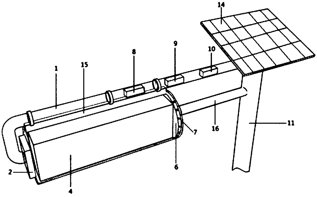
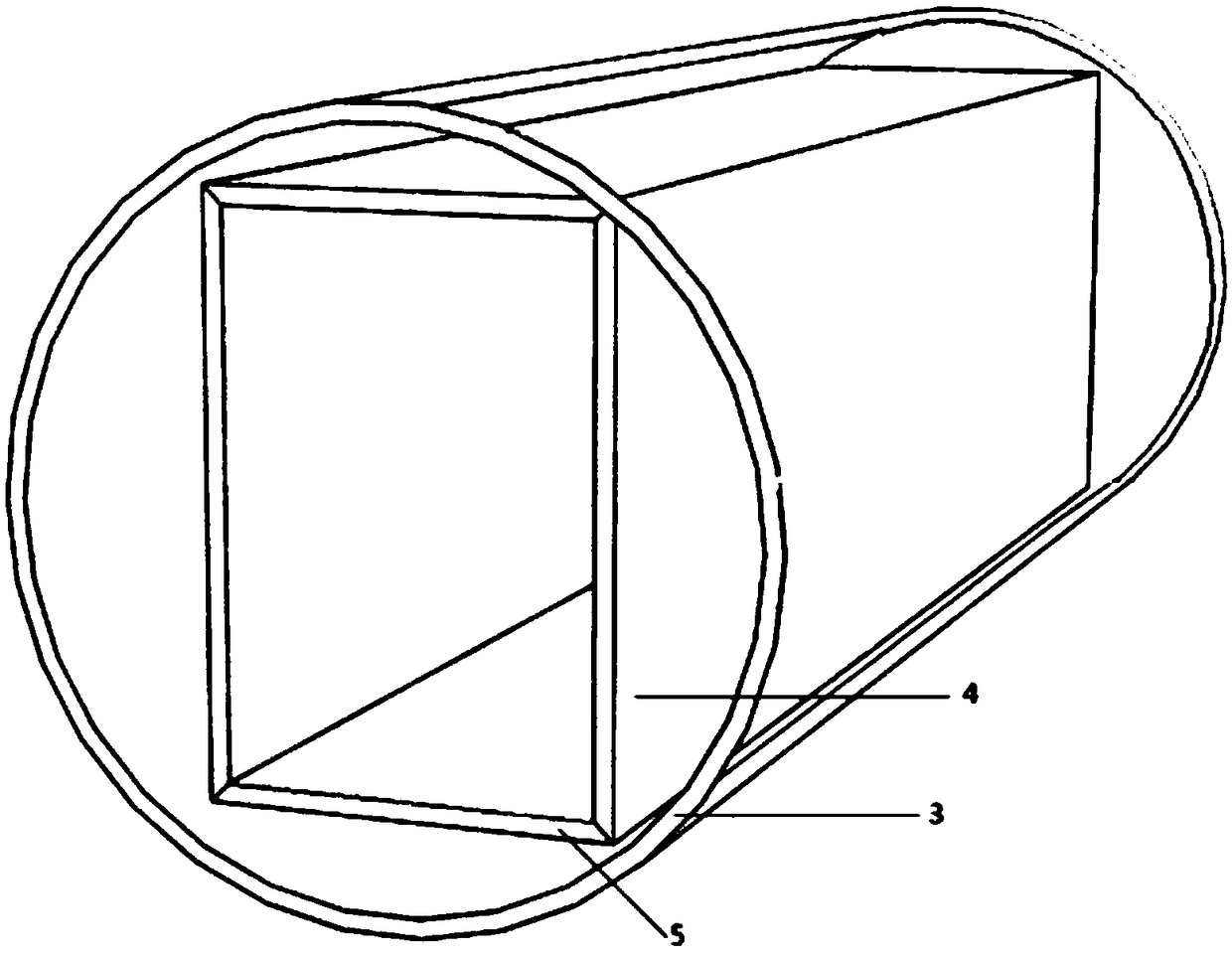
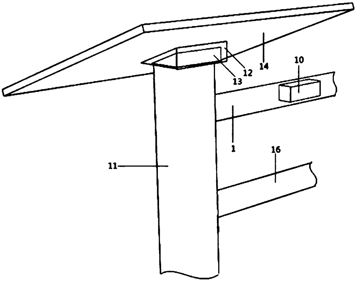
[0016] Such as figure 1 , figure 2 , image 3 As shown, the emergency traffic lights include an L-shaped horizontal beam 1; the left end of the L-shaped horizontal beam 1 is bolted to a power case 2, and the output end of the power case 2 is fixed with a cylindrical transparent protective cover 3; the cylindrical transparent protective cover 3 is internally provided with Hollow tetrahedro...


PUM


Abstract

The invention relates to an emergency traffic signal lamp, which comprises an L-shaped horizontal beam. A power box is bolted at the left end of the L-shaped horizontal beam. A cylindrical transparentprotective cover is fixed at the output end of the power box. A hollow tetrahedron is arranged inside the cylindrical transparent protective cover. Red, yellow and green LED display screens and a piece of transparent organic glass are respectively arranged on the four sides of the hollow tetrahedron. The other end of the cylindrical transparent protective cover is in clearance fit with a circularsupporting plate. Cylindrical rollers are evenly pin-jointed to the circumference of the circular supporting plate. A control circuit set inside the L-shaped horizontal beam is connected with a faultdetection module and a wireless communication module. The emergency traffic signal lamp has the beneficial effects as follows: the emergency traffic signal lamp is simple and convenient to install, has a simple structure, is less prone to mechanical failure and is easy to maintain and repair; and because of the adoption of an automatic detection control technology, the emergency traffic signal lamp responds quickly and has the characteristics such as self-start and remote control.

Description

technical field [0001] The invention relates to the technical field of traffic equipment. Background technique [0002] In traffic equipment, traffic lights are an important part of traffic signals and the basic language of road traffic. Traffic lights are composed of red lights, green lights, and yellow lights. Divided into: motor vehicle signal lights, non-motor vehicle signal lights, crosswalk signal lights, lane signal lights, direction indicator lights, flashing warning lights, road and railway level crossing signal lights, etc. For the traditional traffic lights, it can only realize the indication function of the signal lights, control whether people or vehicles on the road stay or walk, and each traffic signal light is independent of each other, and cannot quickly adjust the traffic lights within a certain range according to real-time road conditions. The indication time of the traffic signal light, if there is a traffic jam on a certain section of the road, the tra...

Claims


Application Information

Patent Timeline
Patent Type & Authority Applications(China)
IPC IPC(8): G08G1/095
CPCG08G1/095
Inventor 陈新宇
Owner 江苏华体照明科技有限公司
Learn More