
Automatic splicing method of ferritic stainless steel for explosive welding

An explosive welding and automatic splicing technology, applied in welding/welding/cutting items, welding equipment, non-electric welding equipment, etc., can solve problems such as low production efficiency, achieve good surface quality, reduce repair steps, and save labor.

Active Publication Date: 2019-02-15
725TH RES INST OF CHINA SHIPBUILDING INDAL CORP
View PDF7 Cites 1 Cited by
  • Summary
  • Abstract
  • Description
  • Claims
  • Application Information

AI Technical Summary

Problems solved by technology

[0004] The purpose of the present invention is to solve the above-mentioned ferritic stainless steel weld seam and heat-affected zone after explosive welding, which causes cracks and crack expansion due to explosion impact, and after the explosion, weld seam planing, resurfacing and other follow-up procedures are required. Steps, the problem of extremely low production efficiency, providing an automatic splicing method for ferritic stainless steel for explosive welding

Method used


Image

  • Automatic splicing method of ferritic stainless steel for explosive welding
  • Automatic splicing method of ferritic stainless steel for explosive welding

Examples


Embodiment 1

[0017] Step 1. Manufacturing of large-area 0Cr13 composite boards. Place the two 06Cr13AL boards to be spliced, with sizes 3*1500*6800 and 3*1300*6800mm, on the tailor welding machine, and remove the oil within 50mm on both sides of the welding boards. , water, rust, oxide layer and other dirt;

[0018] Step 2. Press the test plate to be welded tightly with a piano-type pressing plate, and the gap is controlled between 0 and 0.5mm;

[0019] Step 3. When assembling tack welding, the weld joints should be flush, without misalignment, the length of tack welding should be 7~12mm, and the spacing should be 100~200mm;

[0020] Step 4. Set the plasma welding current to 120~170A, voltage to 20~26V, and welding speed to 200~400mm / min. During the welding process, feed ER321 welding wire continuously, and the diameter of the welding wire is φ0.8mm to ensure that the weld seam is filled. The height is controlled within 0.5~1mm;

[0021] Step 5. After the welding is completed, the weld r...

Embodiment 2

[0026] Step 1. Manufacturing of large-area 0Cr13 composite boards. Place the two 06Cr13 boards to be spliced, with dimensions of 4*1400*5800 and 4*1200*5800mm, on the tailor welding machine, and remove the oil within 50mm on both sides of the welding board. , water, rust, oxide layer and other dirt;

[0027] Step 2. Press the test plate to be welded tightly with a piano-type pressing plate, and the gap is controlled between 0 and 1mm;

[0028] Step 3. When assembling tack welding, the weld joints should be flush, without misalignment, the length of tack welding should be 7~12mm, and the spacing should be 100~200mm;

[0029] Step 4. Set the plasma welding current to 120~170A, voltage to 20~26V, and welding speed to 200~400mm / min. During the welding process, feed ER321 welding wire continuously. The diameter of the welding wire is φ1.2mm to ensure that the weld seam is filled. The height is controlled within 0.5~1mm;

[0030] Step 5. After the welding is completed, the weld re...


PUM


Abstract

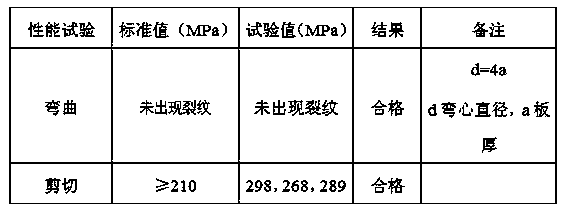
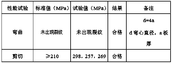
The invention provides an automatic splicing method of ferritic stainless steel for explosive welding. One-time forming is achieved through explosive welding, the surface quality is good, profile control is good, wave deformation is avoided, the property of welding seams meets the requirements of technical evaluation, bending, shearing and other properties can all meet the standard requirements, the repair step in the production process is reduced, thermal cracks and other defects in a welding seamzone and a heat affected zone after explosion welding are avoided, manpower is greatly saved, andthe production cost is saved.

Description

technical field [0001] The invention relates to a material explosive welding splicing process method, in particular to an automatic splicing method of ferritic stainless steel for explosive welding. Background technique [0002] 0Cr13 stainless steel mainly has several grades such as 06Cr13 and 06Cr13Al. This type of stainless steel has excellent heat resistance and is mainly used in coke towers, coal-to-oil and other large-scale petrochemical equipment. The width of stainless steel produced in China is within 1500mm, so it is necessary to splice and widen the stainless steel. Since the stainless steel matrix contains martensitic structure, the weldability is poor, and the welding heat-affected zone is under the action of continuous welding heat cycle. After explosive welding, due to the low plasticity of ferrite itself, as well as the grain growth in the heat-affected zone and the accumulation of carbon and nitride on the grain boundary caused by the welding heat cycle, the...

Claims


Application Information

Patent Timeline
Patent Type & Authority Applications(China)
IPC IPC(8): B23K28/02B23K20/08B23K20/24C21D1/30B23K101/18
CPCB23K20/08B23K20/24B23K28/02C21D1/30
Inventor 任江毅韩刚
Owner 725TH RES INST OF CHINA SHIPBUILDING INDAL CORP
Learn More