
Organic electroluminescent device

An electroluminescent device, an organic technology, applied in the direction of electric solid devices, electrical components, luminescent materials, etc., can solve the problems of device efficiency and life reduction, low oxidation potential hole transfer ability, device life reduction and other problems

Active Publication Date: 2019-02-05
TSINGHUA UNIV
View PDF2 Cites 0 Cited by
  • Summary
  • Abstract
  • Description
  • Claims
  • Application Information

AI Technical Summary

Problems solved by technology

Studies have reported that the reason why many luminescent materials are unstable in the excited state is that the excitation energy is equivalent to the energy of the weakest bond in the molecule, so the weakest bond is easily broken in the excited state, which leads to the degradation of the material and the reduction of the device life. For TADF materials, the weakest bond in the molecule is generally the bond between the electron donor and the linker
On the other hand, the electron donors of most luminescent materials have the problems of low oxidation potential and much higher hole-transporting ability than electron-transporting ability, which makes them prone to charge injection imbalance or oxidation during the working process. It will also lead to a decrease in device efficiency and lifetime.

Method used


Image

  • Organic electroluminescent device
  • Organic electroluminescent device
  • Organic electroluminescent device

Examples


Embodiment 1

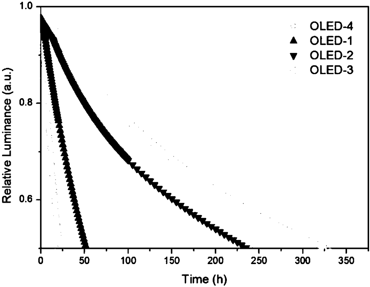
[0097] Embodiment 1: Preparation of OLED-1

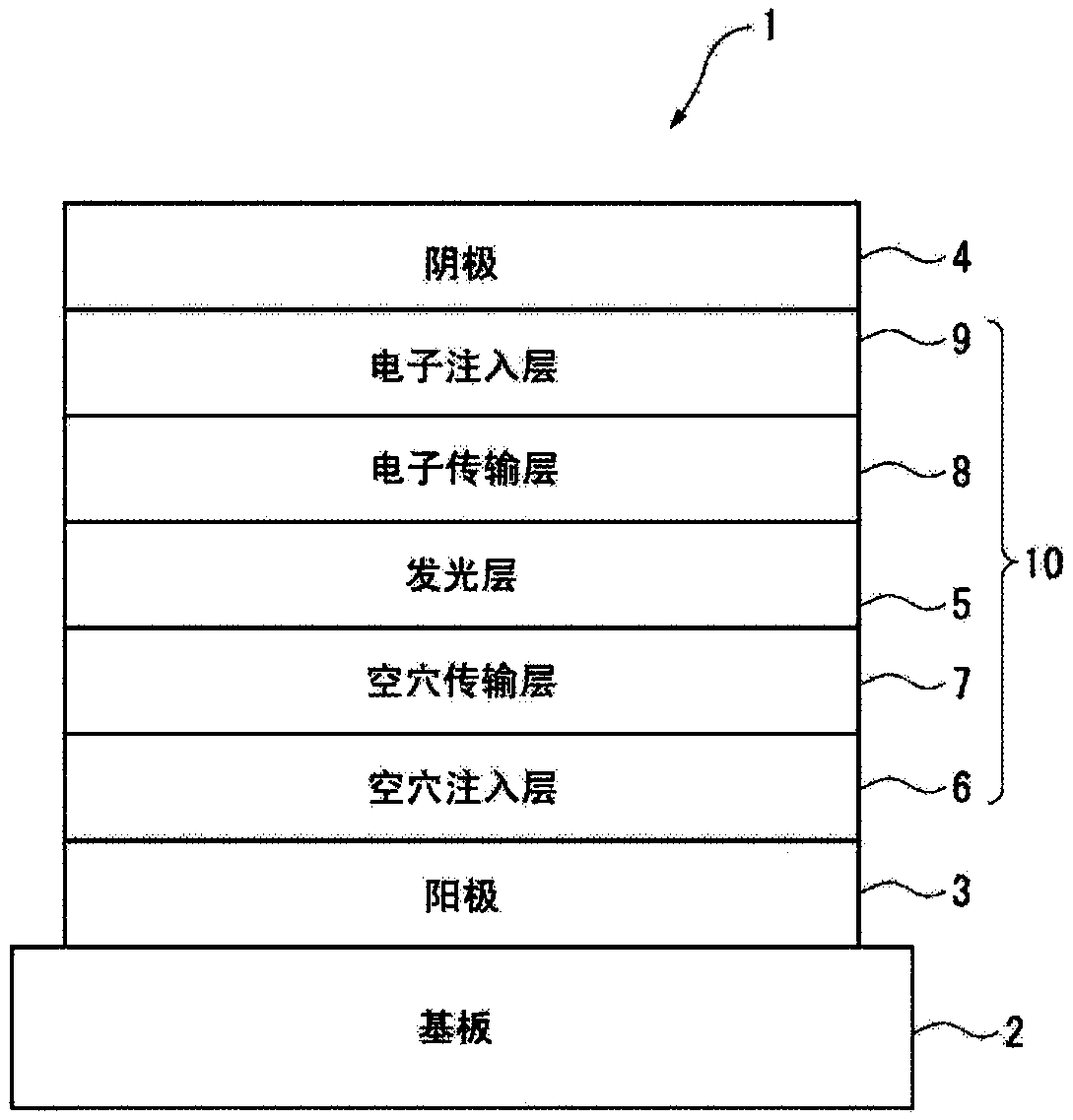
[0098] The glass plate coated with the ITO transparent conductive layer is ultrasonically treated in a cleaning agent, rinsed in deionized water, ultrasonically degreased in acetone and ethanol mixed solvent, baked in a clean environment until the water is completely removed, and then treated with ultraviolet light and ozone cleaning, and bombard the surface of the ITO transparent conductive layer with a low-energy positive ion beam to obtain a glass substrate 2 with an anode 3, wherein the ITO transparent conductive layer is the anode 3.

[0099] Place the above-mentioned glass plate 2 with the anode 3 in the vacuum chamber, and evacuate to 1×10 -5 ~9×10 -3 Pa, HAT-CN was vacuum-deposited on the above-mentioned anode as the hole injection layer 6, the evaporation rate was 0.1nm / s, and the evaporation film thickness was 5nm. Then, NPB with a thickness of 20 nm and TCTA with a thickness of 20 nm were sequentially evaporated at a ra...

Embodiment 2

[0107] Embodiment 2: Preparation of OLED-2

[0108] This embodiment is basically the same as the embodiment 1, the difference is that: the luminescent material is DPEPO: 8%wtC3.

Embodiment 3

[0109] Embodiment 3: Preparation of OLED-3

[0110] This embodiment is basically the same as the embodiment 1, the difference is that: the luminescent material is DPEPO: 8%wtC9.


PUM


Abstract

The present invention provides an organic electroluminescent device comprising a cathode, an anode and an organic thin film layer, and at least one layer of the organic thin film layer comprises a compound represented by the following formula (1) shown in the description, either as a single or as a mixture component. In the formula (1), X is selected from a nitrogen atom or a carbon atom bonded toR1, and C1 to C5 are independently selected from R2-bonded carbon atoms, R1 and R2 are each independently selected from a hydrogen atom, a cyano group, a linear alkyl group or a fluoroalkyl group having 1 to 20 carbon atoms, branched or cyclic alkyl group having 3 to 20 carbon atoms, a substituted or unsubstituted aromatic hydrocarbon group having 6 to 30 carbon atoms, a substituted or unsubstituted heteroaromatic hydrocarbon group having 5 to 30 carbon atoms. The present invention also provides a novel compound selected from the above formula (1). The electrical properties of the organic electroluminescent device of the present invention are very good, and the compound of the formula of the present invention can be used as a luminescent material with excellent stability.

Description

technical field [0001] The invention relates to a novel organic electroluminescent device which can be used in the field of light emission, in particular to an organic electroluminescent device using a novel stable luminescent material. Background technique [0002] Organic electroluminescent devices (hereinafter referred to as OLEDs) have a series of advantages such as self-luminescence, low-voltage DC drive, full curing, wide viewing angle, light weight, simple composition and process. Compared with liquid crystal displays, organic electroluminescent displays are not It needs a backlight source, has a large viewing angle, low power, and its response speed can reach 1000 times that of a liquid crystal display, but its manufacturing cost is lower than that of a liquid crystal display with the same resolution. Therefore, organic electroluminescent devices have broad application prospects. [0003] With the continuous advancement of OLED technology in the two major fields of l...

Claims


Application Information

Patent Timeline
IPC IPC(8): H01L51/50H01L51/54C07D519/00C07D471/04C09K11/06
CPCC09K11/06C07D471/04C07D519/00C09K2211/1029H10K85/6572H10K50/11
Inventor 乔娟王瑞
Owner TSINGHUA UNIV
Learn More