
Baffle plate reinforced fluidized bed external catalyst cooler

A technology of external heat extractor and baffle plate, which is applied in fluidized bed heat exchangers, catalytic cracking, indirect heat exchangers, etc., can solve the problems of poor fluidization state, axial radial temperature, etc., and achieve circumferential radial distribution Uniform, enhanced heat transfer process, easy renovation effect

Pending Publication Date: 2019-01-29
CHINA UNIV OF PETROLEUM (BEIJING)
View PDF17 Cites 1 Cited by
  • Summary
  • Abstract
  • Description
  • Claims
  • Application Information

AI Technical Summary

Problems solved by technology

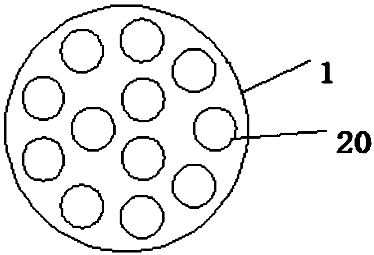
[0009] In view of the above problems, the object of the present invention is to provide a fluidized bed external heat extractor reinforced by baffles. - Solid fluidized bed heat exchange process; the baffle plate optimizes the shell-side flow field of the external heat extractor, strengthens the heat transfer, and solves the problem of axial and radial temperature differences caused by the poor local fluidization state of the shell-side flow field At the same time, the baffle near the catalyst inlet of the external heat extractor rectifies the inlet catalyst, optimizes the distribution of the inlet catalyst, and weakens the erosion and wear of the catalyst at the inlet on the heat exchange tube bundle

Method used


Image

  • Baffle plate reinforced fluidized bed external catalyst cooler
  • Baffle plate reinforced fluidized bed external catalyst cooler
  • Baffle plate reinforced fluidized bed external catalyst cooler

Examples


Embodiment 1

[0044] Such as image 3 As shown, in this embodiment, the baffle 3 adopts a partial conical structure, and the partial conical baffle is a 1 / 4 to 2 / 3 conical panel, and the corresponding cone angle α of the partial conical baffle is 60° to 60°. 150°, the radius R1 of the bottom of the part of the conical baffle is 80% to 95% of the radius of the shell side (the shell side is the inner space of the shell 1 except the wall thickness and heat insulation and wear-resistant layer), and the thickness δ is 3 to 15mm ( Such as image 3 As shown in c); the baffles 3 are helically distributed in the casing 1 along the length direction of the vertical tube bundle 2, and the distance H between adjacent baffles 3 is 150-500mm (such as image 3 shown in a and 3b); by adjusting the spacing H between the baffles 3, the connection form of the adjacent baffles 3 can be adjusted, and according to the influence of the baffles 3 on the flow of the catalyst in the housing 1, considering the relati...

Embodiment 2

[0046] Such as Figure 4 As shown, in this embodiment, the baffle 3 has a partial conical frustum structure. The bottom radius R2 and top radius R3 of the table baffle are respectively 80% to 95% and 15% to 45% of the radius of the shell section, and the thickness δ is 3 to 15mm (such as Figure 4 As shown in c), the baffles 3 are distributed symmetrically and staggered along the length direction of the vertical tube bundle 2 in the shell 1, and the distance H between adjacent baffles 3 is 150-500mm (such as Figure 4 shown in a and 4b); by adjusting the spacing H of the baffles 3, the connection form of the adjacent baffles can be adjusted, that is, whether to overlap, when the spacing H of the adjacent baffles 3 is small, the adjacent baffles 3 Whether they are overlapped or not, the baffles 3 are tightly connected to the vertical tube bundles 2. In this embodiment, the adjacent baffles 3 are non-overlapped. On the basis of part of the conical baffle 3 making the catalyst ...

Embodiment 3

[0048] Such as Figure 5 As shown, in this embodiment, the baffle 3 has an elliptical fan-shaped structure, the central angle β of the elliptical fan-shaped baffle can be 45° to 180°, and the minor axis length a is 80% to 95% of the radius of the shell side section , the length of the major axis b is 1 to 3.85 times the length of the minor axis a, and the thickness δ is 3 to 15 mm (such as Figure 5 As shown in c); the baffles 3 are helically distributed or symmetrically staggered along the length direction of the vertical tube bundle 2 in the shell 1, and the distance H between two adjacent elliptical fan-shaped baffles is 150-500mm (such as Figure 5 a and 5b), the connection form of adjacent baffles can be adjusted by adjusting the spacing H of the baffles 3, that is, whether they are overlapped or not. In this embodiment, the baffles are in a non-overlapped form. The baffle makes the catalyst add spiral flow or radial cross-flow flow on the basis of the axial flow, and ma...


PUM

PropertyMeasurementUnit
thicknessaaaaaaaaaa
angleaaaaaaaaaa

Abstract

The invention discloses a baffle plate reinforced fluidized bed external catalyst cooler. The baffle plate reinforced fluidized bed external catalyst cooler comprises a shell, a vertical tube bundle,baffle plates, and a gas distributor; a catalyst inlet is formed in the upper portion of the shell, a catalyst outlet is formed in the bottom of the shell, the vertical tube bundle comprises multipleheat exchange pipes vertically distributed in the shell, each heat exchange pipe comprises a water pipe and a steam pipe arranged outside the water pie in a sealed sleeving manner, the top end of eachheat exchange pipe extends out of the outer portion of the shell, the top of each water pipe is provided with a water inlet, steam outlets are formed in the tops of the steam pipes, the baffle platesare spirally arranged or symmetrically arranged in a staggered manner in the shell in the length direction of the vertical tube bundle, the heat exchange pipes penetrate through the baffle plates andare in fastened connection with the baffle plates, the baffle plates and the vertical tube bundle are connected into a whole, the gas distributor is arranged at the position, below the vertical tubebundle, in the shell, and a fluidizing air inlet communicating with the gas distributor is formed in the shell.

Description

technical field [0001] The invention relates to an external heat extractor for a fluidized bed, in particular to an external heat extractor for a fluidized bed strengthened by baffle plates, and belongs to the technical fields of petroleum processing and chemical industry. Background technique [0002] my country's catalytic cracking raw materials continue to be heavy, and the increase in coke formation rate makes the heat surplus of the regeneration system, and it is necessary to remove the excess heat in time to maintain the heat balance of the reverse regeneration system. In addition, in order to improve the yield of the target product and the benefit of the enterprise, it is necessary to flexibly increase the catalyst-oil ratio of catalytic cracking as much as possible without reducing the feed temperature, and it is also necessary to properly cool the high-temperature regenerated catalyst. Therefore, it is very important to remove the excess heat carried by the catalyst...

Claims


Application Information

Patent Timeline
Patent Type & Authority Applications(China)
IPC IPC(8): F28D13/00B01J19/00C10G11/18
CPCB01J19/00F28D13/00C10G11/18
Inventor 卢春喜李建涛姚秀颖刘璐
Owner CHINA UNIV OF PETROLEUM (BEIJING)
Learn More