Cone stop valve

A globe valve and cone surface technology, applied in the field of cone surface globe valves, can solve the problems of troublesome assembly process, low production efficiency, large torque, etc., and achieve the effect of preventing corrosion risk, reducing operating torque and improving resistance.

Inactive Publication Date: 2019-01-29
EAST CHINA MINING EQUIP CO LTD
View PDF3 Cites 2 Cited by
  • Summary
  • Abstract
  • Description
  • Claims
  • Application Information

AI Technical Summary

Problems solved by technology

Usually, the valve stem of the cone globe valve is connected to the valve core through a screw sleeve. The structure of this connection method is complicated, the assembly process is troublesome, the production efficiency is low, and the torque is large during operation, which is laborious.

Method used


Image

  • Cone stop valve
  • Cone stop valve

Examples


Embodiment Construction

[0016] Through the description of the embodiments below, the specific implementation of the present invention includes the shape, structure, mutual position and connection relationship between the various parts, the function and working principle of each part, the manufacturing process and the operation and use method of the various components involved. etc., to make further detailed descriptions to help those skilled in the art have a more complete, accurate and in-depth understanding of the inventive concepts and technical solutions of the present invention.

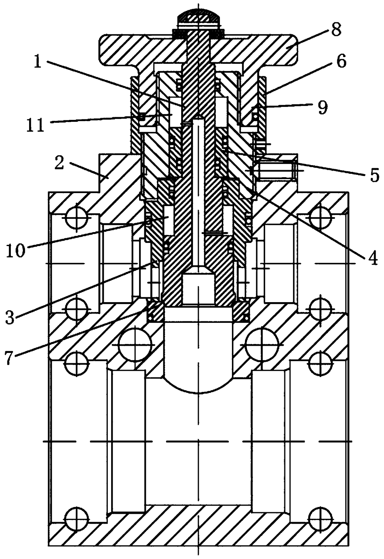
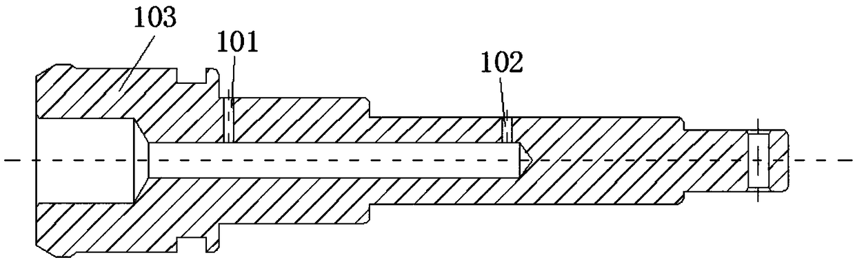
[0017] Such as Figure 1 to Figure 2 As shown, a cone cut-off valve includes a valve body 2, a valve stem 1, a valve sleeve 3, a screw sleeve 4, a hand wheel and a valve stem sleeve 5, the valve body 2 is provided with a valve sleeve 3, and the valve The sleeve 3 is sleeved on the valve stem 1, and a first balance chamber 10 for the liquid to enter is formed between the valve sleeve 3 and the valve stem 1. The screw sl...


PUM


Abstract

The invention discloses a cone stove valve and relates to the technical field of mining valves. The cone stop valve comprises a valve body, a valve rod, a valve bushing, a barrel, a hand wheel and a valve rod bushing, wherein the valve bushing is arranged in the valve body and sleeves the valve rod, and a first balance cavity for allowing liquid to flow into is formed between the valve bushing andthe valve rod; the barrel is connected with the valve body and sleeves the valve rod; the valve rod bushing is arranged inside the barrel and sleeves the valve rod, and a second balance cavity for allowing the liquid to flow into is reserved between the barrel and the valve rod bushing; the valve rod is provided with a damping channel for allowing the liquid to flow into and enabling the first balance cavity and the second cavity to communicate with each other; and the hand wheel is connected with the valve rod. Through arrangement of the first balance cavity and the second balance cavity, resistance generated when the hand wheel is screwed in the opening or closing process of the cone stop valve is greatly reduced, operation torque can be reduced so that labor for operation can be saved,and meanwhile, by means of a dust hood, complicated conditions under a mine are isolated and the situation that the hand wheel is exposed in the severe condition and contaminated to result in the rusting risk is prevented.

Description

technical field [0001] The invention belongs to the technical field of mine valves, in particular to a cone stop valve. Background technique [0002] The cone stop valve is a kind of stop valve, which is widely used in the hydraulic circuit of the hydraulic support of the coal mine fully mechanized mining face. Usually, the valve stem of the cone globe valve is connected to the valve core through a screw sleeve. This connection method has a complex structure, troublesome assembly process, low production efficiency, and large torque during operation, which is laborious. Contents of the invention [0003] Based on the above deficiencies in the prior art, the technical problem to be solved by the present invention is to provide a cone stop valve to solve all or one of the problems mentioned in the background technology. [0004] In order to solve the problems of the technologies described above, the technical solution adopted in the present invention is: [0005] A conical ...

Claims


Application Information

Patent Timeline
Patent Type & Authority Applications(China)
IPC IPC(8): F16K1/38F16K1/32F16K27/08F16K27/12F16K31/60
CPCF16K1/32F16K1/385F16K27/08F16K27/12F16K31/607
Inventor 王剑飞
Owner EAST CHINA MINING EQUIP CO LTD
Why Eureka
Try Eureka