
Device for aircraft simulation catapulting test

A technology of aircraft simulation and test equipment, which is applied in the field of aircraft simulation ejection test, can solve the problems of lowering the launch platform, prone to leakage, and affecting the safety of the test, so as to achieve the effect of ensuring absolute safety and improving stability

Pending Publication Date: 2019-01-29
芜湖航翼集成设备有限公司
View PDF1 Cites 2 Cited by
  • Summary
  • Abstract
  • Description
  • Claims
  • Application Information

AI Technical Summary

Problems solved by technology

[0003] For example, Chinese Patent Publication No. CN201410231086.9 discloses an ejection additional load simulation test system. The fluid is injected from the injection port, and the pressure of the injected fluid is measured by the pressure measuring device. After the fluid is injected into the guide cylinder, the pressure of the flexible base will Elastic deformation occurs, which will cause mutual movement in the vertical direction between the guide cylinder and the sliding cylinder. The tension sensor fixedly connected to the guide cylinder and the sliding cylinder can therefore measure the size of the additional load generated during the mutual movement. The system is mainly used for static simulation tests. Based on the test data, a launch platform with a more optimized structure can be designed to control the size of the additional load within a certain range, minimize the load on the launch platform during ejection, and effectively improve the launch. The ejection stability and safety of the platform, but the patent uses fluid as a pressure test, which is prone to leakage and affects the safety of the test

Method used


Image

  • Device for aircraft simulation catapulting test
  • Device for aircraft simulation catapulting test
  • Device for aircraft simulation catapulting test

Examples


Embodiment Construction

[0031] In order to make the technical means, creative features, goals and effects achieved by the present invention easy to understand, the present invention will be further elaborated below.

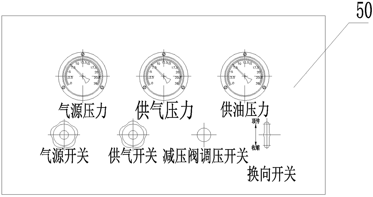
[0032] Such as Figure 1 to Figure 14 As shown, a device for simulated ejection test of an aircraft comprises a control cabinet 1 for control, a test frame 4 cooperating with the control cabinet 1, a platform vehicle 5 arranged at the lower end of the test frame 4, and on the test frame 4 A hooking device for hooking the aircraft is provided, and the test stand 4 is also provided with a simulation device for realizing the simulated ejection test of the aircraft. The control cabinet 1 is equipped with a hydraulic system 3 and a pneumatic system for realizing hydraulic pressure and pneumatic power. System 2.

[0033] The hooking device is arranged on the test frame 4 for hooking the aircraft; the simulation device is arranged on the test frame 4 for realizing the simulated ejection test ...


PUM


Abstract

The invention relates to the field of aircraft simulation catapulting tests, specifically to a device for an aircraft simulation catapulting test. The device for the aircraft simulation catapulting test comprises a control cabinet, a test frame and a platform truck, wherein the control cabinet is used for controlling; the test frame is matched with the control cabinet; the platform truck is arranged at the lower end of the test frame; a hooking device used for hooking an aircraft is arranged on the test frame; a simulation device used for realizing the aircraft simulation catapulting test is also arranged on the test frame; and a hydraulic system and a pneumatic system which are used for realizing hydraulic and pneumatic functions are embedded in the control cabinet. A foundation bolt is poured with ground cement to realize the stability of the test frame during testing; and meanwhile, the stability is improved under the coordination of a shock absorption mechanism so that the absolutesafety in the testing process is guaranteed; in order to limit the contracting velocity of an acting cylinder, the stability, safety and reliability of the acting cylinder in the whole contracting process can be guaranteed under the coordination of a throttle valve.

Description

technical field [0001] The invention relates to the field of aircraft simulated ejection tests, in particular to an aircraft simulated ejection test device. Background technique [0002] Before the real flight, the aircraft needs to conduct various tests under different environmental conditions. It needs to conduct flight tests in all stages of research, design, appraisal, production and use. With the help of a large number of accurate measurement methods, the actual test data can be obtained. , especially in the simulated ejection test of the aircraft, it is necessary to bear the instantaneous impact load of 50KN acting upward in the test. In order to avoid the possible harm caused by the instantaneous impact load, the test frame needs to be protected in advance with stability and buffering. [0003] For example, Chinese Patent Publication No. CN201410231086.9 discloses an ejection additional load simulation test system. The fluid is injected from the injection port, and th...

Claims


Application Information

Patent Timeline
IPC IPC(8): B64F5/60
CPCB64F5/60
Inventor 邢朝华赵桂芳张茂杉管志鹏杨占鹏
Owner 芜湖航翼集成设备有限公司
Learn More