Hybrid four-gear transmission driving system

A hybrid power and drive system technology, applied in hybrid vehicles, power devices, pneumatic power devices, etc., can solve the problems of single end speed ratio of permanent magnet synchronous motors, poor driving comfort, and inability to shift gears, etc., to achieve convenience Design layout, good driving comfort, and the effect of eliminating impact

Pending Publication Date: 2019-01-29
KUNTAI VEHICLE SYST CHANGZHOU CO LTD
View PDF0 Cites 1 Cited by
  • Summary
  • Abstract
  • Description
  • Claims
  • Application Information

AI Technical Summary

Problems solved by technology

[0003] Most of the existing hybrid transverse transmission drive systems use permanent magnet synchronous motors to provide power directly to the final reduction gear of the differential or input to the input outer shaft of the engine. When the permanent magnet synchronous motor does not need to be involved in the vehicle, the permanent magnet synchronous motor will also rotate, that is to say, the permanent magnet synchronous motor is "dragged", and the permanent magnet synchronous motor rotor will bring Moment of inertia, if the moment of inertia is too large, it will affect the gear shifting, which will produce a sense of shock, make the whole vehicle vibrate, and cause poor driving comfort
Moreover, the existing hybrid vehicle cannot shift gears when running purely on electric power, and the gear position is relatively simple. Furthermore, in the process of energy recovery, because the speed ratio of the permanent magnet synchronous motor end is relatively simple, it cannot be adjusted according to the road conditions and the energy of the vehicle. It is necessary to change the speed ratio, and the speed ratio change cannot be performed in real time, that is to say, the energy recovery cannot be carried out in sections and quantitatively according to the energy demand of the road conditions, so as not to save energy and cause waste
At this time, if the control system is inaccurate, the energy demand and supply of the whole vehicle will be unbalanced, which will cause the whole vehicle to shake

Method used


Image

  • Hybrid four-gear transmission driving system
  • Hybrid four-gear transmission driving system
  • Hybrid four-gear transmission driving system

Examples


Embodiment Construction

[0034] The present invention will be described in detail below in conjunction with specific embodiments shown in the accompanying drawings. However, these embodiments are not limited to the present invention, and structural, method, or functional changes made by those skilled in the art according to these embodiments are included within the protection scope of the present invention.

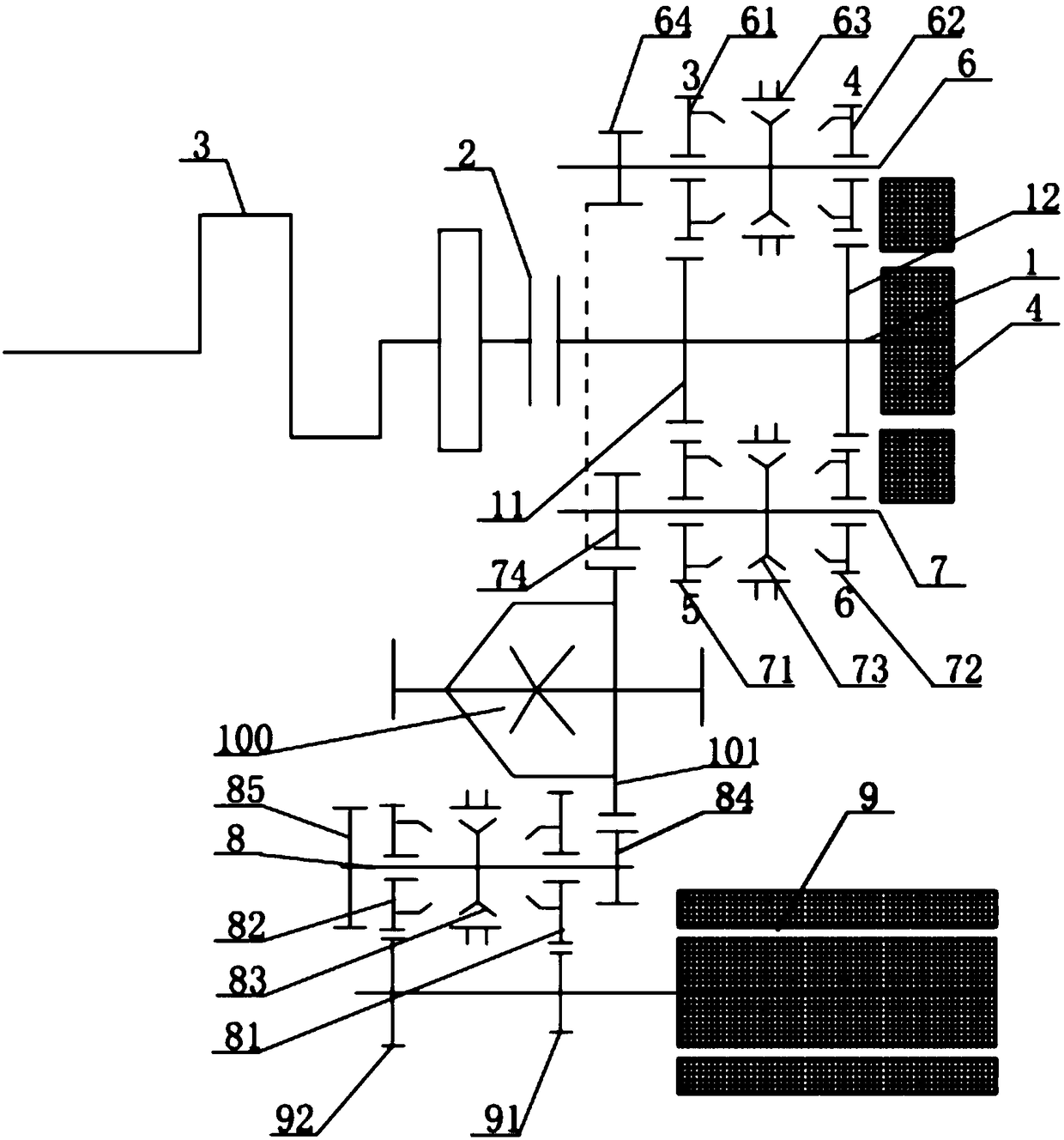
[0035] Such as figure 1 As shown, the present invention discloses a hybrid four-speed transmission drive system, including a differential 100, the final reduction gear 101 of the differential 100 can be driven by a hybrid drive assembly or / and a pure electric drive assembly, the The final reduction gear 101 of the differential 100 is connected to the hub of the vehicle.

[0036]In the present invention, the pure electric drive assembly at least includes a main drive motor 9 and a third output shaft 8 arranged on one side of the differential 100, and the motor shaft of the main drive motor 9 is f...


PUM


Abstract

The invention discloses a hybrid four-gear transmission driving system. The hybrid four-gear transmission driving system comprises a differential mechanism; a main reduction gear of the differential mechanism can be driven by a hybrid driving component and / or a pure electric driving component; the pure electric driving component at least comprises a main driving motor and a third output shaft; anE first-gear driving gear and an E second-gear driving gear are fixedly arranged on a motor shaft of the main driving motor; an E first-gear driven gear engaged with the E first-gear driving gear andan E second-gear driven gear engaged with the E second-gear driving gear are arranged on a third output shaft; and an E synchronizer arranged on the third output shaft is also arranged between the E first-gear driven gear and the E second-gear driven gear. The hybrid four-gear transmission driving system has the beneficial effects that the system can run under a pure electric condition; the gear has two gear options; and the gears can be switched according to needs to reduce requirements on the main driving motor. The impact sense can be eliminated, the whole vehicle cannot shake during running, and the driving and taking comfort is better.

Description

technical field [0001] The invention relates to the technical field of hybrid electric vehicles, in particular to a driving system of a hybrid four-speed transmission. Background technique [0002] With the increasing shortage of oil supply and the increasing environmental pollution, the hybrid transverse transmission drive system with good fuel economy, low emission, fuel saving rate and power has attracted more and more attention. [0003] Most of the existing hybrid transverse transmission drive systems use permanent magnet synchronous motors to provide power directly to the final reduction gear of the differential or input to the input outer shaft of the engine. , that is, when the vehicle does not need the intervention of the permanent magnet synchronous motor, the permanent magnet synchronous motor will also rotate, that is to say, the permanent magnet synchronous motor is "dragged", and the permanent magnet synchronous motor rotor will bring The moment of inertia, if...

Claims


Application Information

Patent Timeline
Patent Type & Authority Applications(China)
IPC IPC(8): B60K6/54B60K6/36B60K6/547B60K6/387B60K6/48B60K6/485B60K6/383B60K6/40
CPCB60K6/36B60K6/383B60K6/387B60K6/40B60K6/48B60K6/485B60K6/54B60K6/547B60K2006/4825Y02T10/62
Inventor 惠无垠梁志海张兴林
Owner KUNTAI VEHICLE SYST CHANGZHOU CO LTD
Why Eureka
Try Eureka