
An etching method for improving the etching ability of the end face of a semiconductor silicon wafer

A technology for semiconductors and silicon wafers, which is applied in semiconductor/solid-state device manufacturing, electrical components, circuits, etc. It can solve the problems of uneven corrosion, cost loss, and inconsistent corrosion rate on the end surface of silicon wafers, and achieve the reduction of SiO2 film residue on the end surface, The effect of saving usage and reducing cost

Inactive Publication Date: 2019-01-18
杭州中欣晶圆半导体股份有限公司 +1
View PDF6 Cites 0 Cited by
  • Summary
  • Abstract
  • Description
  • Claims
  • Application Information

AI Technical Summary

Problems solved by technology

If the contact part is a non-polished surface, it will affect the end face corrosion rate of the silicon wafer
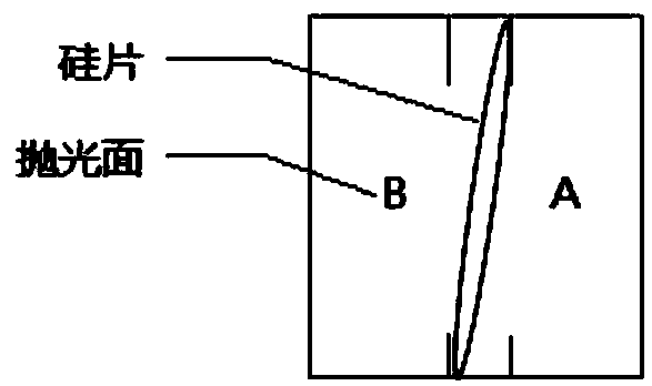
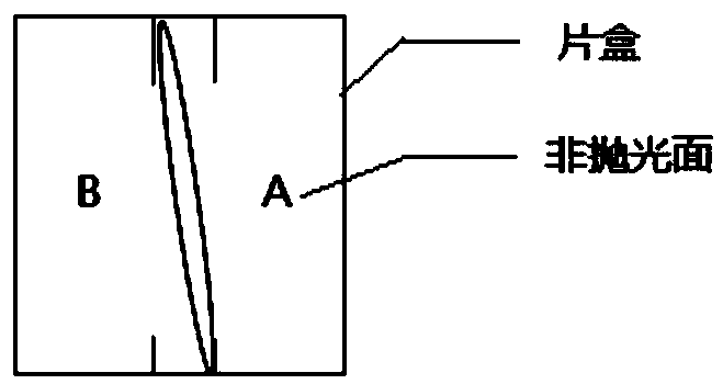
Compared with the non-contact parts, the corrosion rate of the silicon wafer and the contact part of the box is inconsistent, which may cause SiO2 on the end face 2 Residual film, abnormal chamfer profile on the end face; uneven corrosion on the end face of the silicon wafer, abnormal surface condition
As a result, the rate of silicon wafer rework and scrap increases, the amount of corrosion liquid used increases, and the yield rate decreases, resulting in unnecessary cost losses

Method used


Image

  • An etching method for improving the etching ability of the end face of a semiconductor silicon wafer
  • An etching method for improving the etching ability of the end face of a semiconductor silicon wafer
  • An etching method for improving the etching ability of the end face of a semiconductor silicon wafer

Examples


Embodiment Construction

[0046] The present invention will be further described below in conjunction with the accompanying drawings.

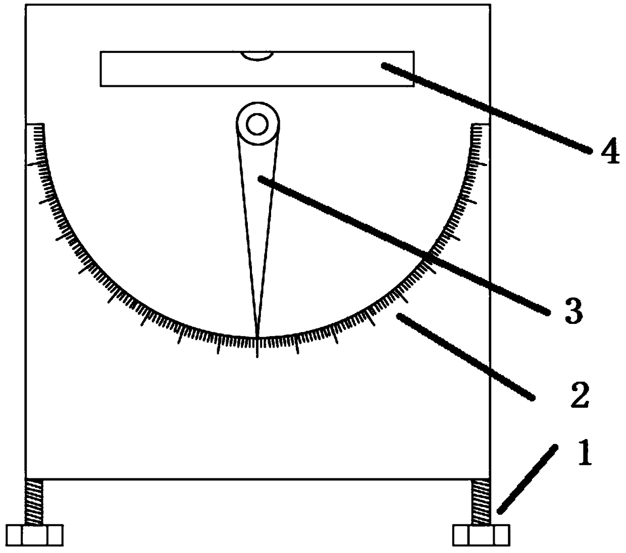
[0047] see image 3 , Figure 4 as well as Figure 5 , an etching method for improving the corrosion ability of semiconductor silicon wafer end faces, comprising the following steps: step 1, silicon wafers are loaded into a cassette, and the orientations of the polished surfaces of the silicon wafers in the cassette are consistent; The bottom plate of the treatment tank where the chip is corroded is set at an inclination, and the inclination angle formed by the bottom plate and the horizontal plane ranges from 1 to 10°; the four corners of the treatment tank are provided with threaded holes that open downward, and screws are installed in the threaded holes. , adjust the inclination of the bottom plate of the processing tank by screwing the screw into the threaded hole; Step 3, place the cassette in the processing tank, because the bottom plate of the processing tank ...


PUM


Abstract

The invention relates to the field of semiconductor manufacturing. An etch method for improving that etchING ability of the end face of a semiconductor silicon wafer comprises the following step: step1, the silicon wafer is loaded into a wafer cassette, and the orientation of the polishing surface of the silicon wafer in the wafer cassette is consistent; 2, that bottom plate of the proces groovefor etching the silicon wafer is inclined, and the angle range of the inclination angle formed by the bottom plate and the horizontal plane is 1 to 10 degrees; The four corners of the processing groove are provided with threaded holes with downward opening, screws are arranged in the threaded holes, and the screw is screwed into the threaded holes to adjust the inclination degree of the bottom plate of the processing groove; 3, place that wafer box in the processing groove, wherein the polishing surface of the silicon wafer faces downward due to the inclination of the bottom plate of the processing groove; Step 4, the silicon wafer in the treatment groove is subjected to an end surface etching process. As that cartridge can be incline at an angle when the cartridge is placed on the bottomplate, the polis surface of the silicon wafer in the cartridge is designated to face downward, thereby avoiding the influence of the contact of the edge of the non-polishing surface with the cartridgeon the etching rate.

Description

technical field [0001] The invention relates to the field of semiconductor manufacturing, in particular to a silicon wafer etching method. Background technique [0002] In the production and processing of semiconductor silicon wafers, end face etching is one of the common end face treatment technologies at present. Its basic principle is to use HF acid to react with Si without chemical reaction and to react with SiO 2 The nature of the reaction, the end face is etched in the end face treatment tank to remove the SiO on the end face of the silicon wafer after APCVD film formation. 2 The purpose of the film. [0003] In the prior art, silicon wafers are first placed vertically in a cassette, and then the wafer cassette and silicon wafers are vertically placed in an end surface treatment tank for etching. The silicon wafer rests on the edge of the cassette under the force of gravity. Due to the horizontal design of the bottom plate of the etching tank, the bottom of the cas...

Claims


Application Information

Patent Timeline
Patent Type & Authority Applications(China)
IPC IPC(8): H01L21/02
CPCH01L21/02019
Inventor 戚定定贺贤汉庄云娟
Owner 杭州中欣晶圆半导体股份有限公司
Learn More