a sensor
A sensor and magnetoresistive sensor technology, applied in the field of measurement, can solve the problem of low detection sensitivity of magnetoresistive sensors
- Summary
- Abstract
- Description
- Claims
- Application Information
AI Technical Summary
Problems solved by technology
Method used
Image
Examples
Embodiment 1
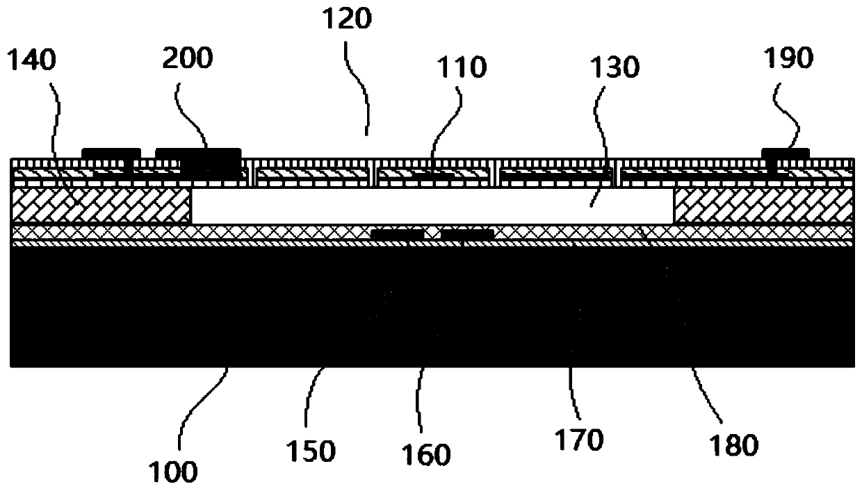
[0056] Specifically, in one embodiment of the present invention, refer to image 3 , the present invention provides a microphone, which includes a first substrate 100 and a diaphragm 120 supported above the first substrate 100 through a first spacer 140, the first substrate 100, the first spacer 140, the diaphragm 102 encloses a vacuum cavity 130 .
[0057] The first substrate 100 of the present invention can be made of single crystal silicon or other materials well known to those skilled in the art, and the first spacer 140 can be formed by layer-by-layer deposition, patterning, and sacrificial processes, and the first spacer 140 can be formed through the first spacer 140 The diaphragm 120 supported on the first substrate 100 and the vacuum chamber 130 can be sealed by, for example, low-pressure plasma-enhanced chemical vapor deposition (PECVD) at 200-350°C. This MEMS process belongs to the common knowledge of those skilled in the art, and will not be described in detail her...
Embodiment 2
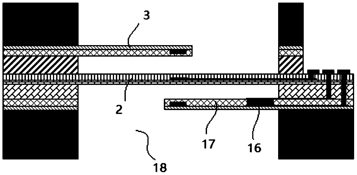
[0078] refer to Figure 4 , the difference from Embodiment 1 is that in this embodiment, the first substrate 100 has a hollow cavity 101 communicating with the outside world, and also includes a cantilever 171 separated from the diaphragm 120, the edge of the diaphragm 120 and the edge of the cantilever 171 The terminals are directly or indirectly connected to the first substrate 100 , so that the diaphragm 120 and the main part of the cantilever 171 are suspended above the cavity 101 in the first substrate 100 .
[0079] The cantilever 171 is separated from the diaphragm 120 by a first spacer, and the height of the first spacer is the initial gap between the diaphragm 120 and the cantilever 171 . Since the structure of the back plate is abandoned, the structural design of the cantilever 171 is adopted, so that the diaphragm 120, the first spacer and the cantilever 171 form an open cavity, and the cantilever 171 will not seal the cavity. This is completely different from the ...
Embodiment 3
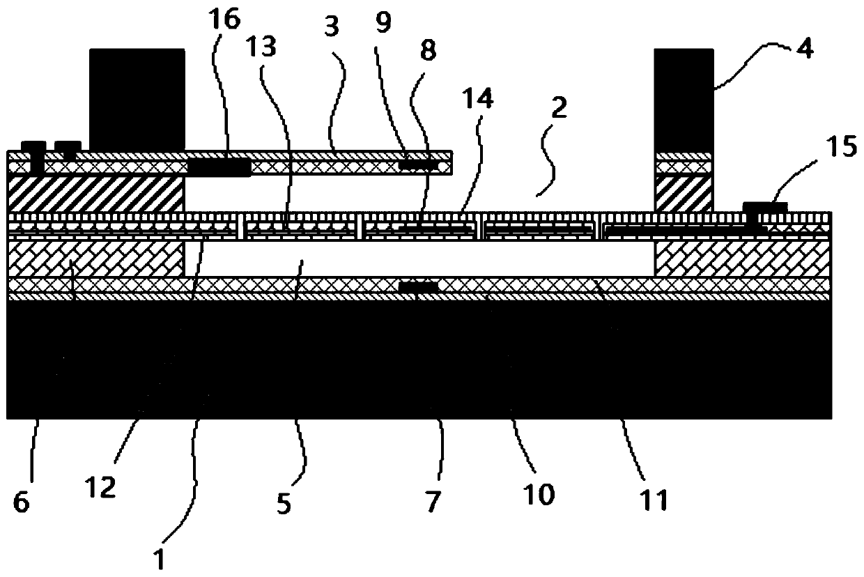
[0091] refer to figure 1 , the present invention provides a microphone, which includes a first substrate 1 and a diaphragm 2 supported above the first substrate 1 by a first spacer 6, the first substrate 1, the first spacer 6, the diaphragm 2 has surrounded the vacuum chamber 5.
[0092] The first substrate 1 of the present invention can be made of single crystal silicon or other materials well known to those skilled in the art, and the first spacer 6 can be formed by layer-by-layer deposition, patterning, and sacrificial processes, and the first spacer 6 can be formed through the first spacer 6 The diaphragm 2 supported on the first substrate 1 and the vacuum cavity 5 can be sealed by, for example, low-pressure plasma-enhanced chemical vapor deposition (PECVD) at 200-350°C. This MEMS process belongs to the common knowledge of those skilled in the art, and will not be described in detail here. Wherein the vacuum chamber 5 is preferably less than 1 kPa, which makes the visco...
PUM
 Abstract
Description
Claims
Application Information
 - R&D
- Intellectual Property
- Life Sciences
- Materials
- Tech Scout
- Unparalleled Data Quality
- Higher Quality Content
- 60% Fewer Hallucinations
Browse by: Latest US Patents, China's latest patents, Technical Efficacy Thesaurus, Application Domain, Technology Topic, Popular Technical Reports.
© 2025 PatSnap. All rights reserved.Legal|Privacy policy|Modern Slavery Act Transparency Statement|Sitemap|About US| Contact US: help@patsnap.com


