Al technical title is built by PatSnap Al team. It summarizes the technical point description of the patent document.
A pipe feeding machine and automatic technology, which is applied in metal processing equipment, feeding devices, manufacturing tools, etc., can solve the problems of pipes being unable to be conveyed into the cavity, and achieve the effect of preventing interference and ensuring safe transportation
Active Publication Date: 2019-01-15
厦门凌睿工贸有限公司
View PDF9 Cites 11 Cited by
Summary
Abstract
Description
Claims
Application Information
AI Technical Summary
This helps you quickly interpret patents by identifying the three key elements:
Problems solved by technology
Method used
Benefits of technology
Problems solved by technology
[0004] Among them, when placing the pipe, the staff needs to manually put the metal pipe into the lower mold and ensure that the placement of the pipe is accurate. Therefore, it is necessary to specially equip a staff member to place the metal pipe. In the prior art, it has been developed for intermittent delivery. A pipe conveyor for pipes, such as a pipe conveyor disclosed in a Chinese patent with the authorized announcement number CN206955182U, which specifies the working principle of the pipe conveyor; Interference means that it is impossible to directly set the discharge end in the lower mold, so the existing pipe conveyor cannot convey the pipe into the cavity
Method used
Image
Click on the blue label to locate the original text in one second.
Reading with bidirectional positioning of images and text.
Examples
Embodiment Construction
[0040] The present invention will be described in detail below in conjunction with the accompanying drawings and embodiments.
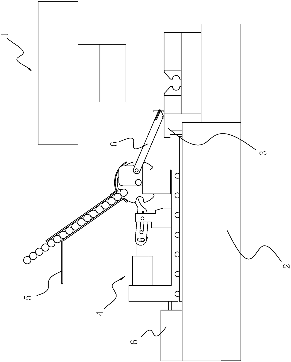
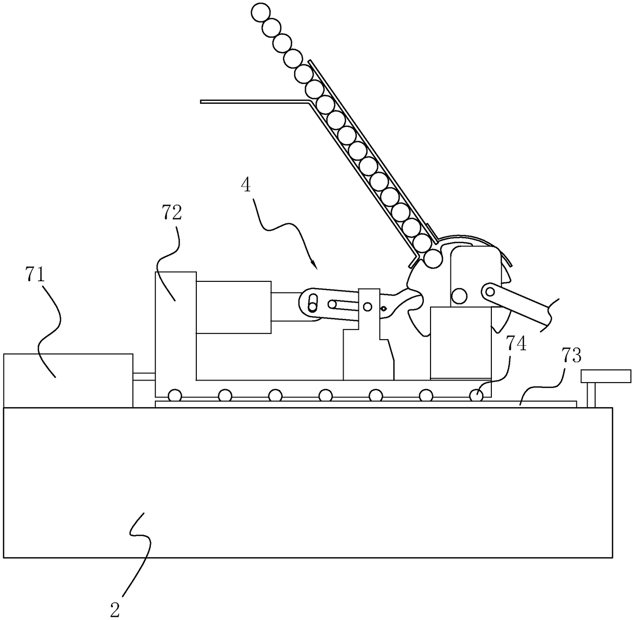
[0041] An automatic pipe feeding machine, such as figure 1 As shown, it includes a machine base 2 set on the ground, an extension plate 3 set on the machine base 2 and one side of which is closely attached to the side wall of the lower die, and slidably connected to the machine base 2 for intermittently conveying pipes To the transfer assembly 4 in the stamping mold 1, set on the transfer assembly 4 to transport the pipe material to the lower hopper 5 in the transfer assembly 4, set obliquely, and set the upper and lower ends respectively at the discharge end and extension of the transfer assembly 4 The upper surface of the plate 3 is used to guide the pipe to slide from the transfer assembly 4 to the guide plate 6 in the cavity, and it is arranged on the machine base 2 to push the transfer assembly 4 and the guide plate 6 to slide back and forth in t...
PUM
Abstract
The invention discloses an automatic pipe feeder, and relates to the technical field of mold production auxiliary equipment, and the technical problem that the pipes are conveyed into the cavity by apipe conveyor is solved. The feeder comprises a machine base arranged on the ground, an extension plate which is arranged on the machine base and is tightly attached to the side wall of a lower mold,a transfer assembly which is slidably connected to the machine base and is used for intermittently conveying pipes into a stamping forming mold, a lower hopper which is arranged in the transfer assembly and used for conveying the pipes to the transfer assembly, a guide plate which is inclinedly arranged, and having the upper and lower ends respectively arranged at the discharging end of the transfer assembly and the upper surface of the extension plate to guide the pipes to slide from the transfer assembly to the cavity, and a pushing mechanism which is arranged on the machine base and used for pushing the transfer assembly and the guide plate to slide back and forth in the stamping forming direction. The automatic pipe feeder has the advantages that the metal pipes can be accurately conveyed into the cavity.
Description
technical field [0001] The invention relates to the technical field of auxiliary equipment for mold production, more specifically, it relates to an automatic pipe feeding machine. Background technique [0002] In the prior art, it is often necessary to use various metal pipes, such as steel pipes, aluminum pipes, iron pipes, etc., and according to needs, it is often necessary to bend, flatten, and punch various metal pipes. Various types of equipment are required, such as bending machines, punching machines, flattening machines, etc. Among them, bending machines, punching machines, and flattening machines are more targeted, so they can only perform single processing tasks , and some metal pipes often need to be combined with multiple tasks such as bending, punching, and flattening. If the operations are performed separately, it will not only take more time, but also affect labor costs and product quality. Therefore, for some metal pipes with relatively auxiliary structures,...
Claims
Application Information
Patent Timeline
Application Date:The date an application was filed.
Publication Date:The date a patent or application was officially published.
First Publication Date:The earliest publication date of a patent with the same application number.
Issue Date:Publication date of the patent grant document.
PCT Entry Date:The Entry date of PCT National Phase.
Estimated Expiry Date:The statutory expiry date of a patent right according to the Patent Law, and it is the longest term of protection that the patent right can achieve without the termination of the patent right due to other reasons(Term extension factor has been taken into account ).
Invalid Date:Actual expiry date is based on effective date or publication date of legal transaction data of invalid patent.