Ceramic mechanical powder mill

A kind of milling machine and mechanical technology, which is applied in the direction of grain processing, etc., can solve the problems of large limitations and difficult ceramic particles to be evenly ground, and achieve the effect of improving production efficiency and saving processing time

Active Publication Date: 2019-01-15
景德镇市珏昊瓷业有限公司
View PDF8 Cites 10 Cited by
  • Summary
  • Abstract
  • Description
  • Claims
  • Application Information

AI Technical Summary

Problems solved by technology

The utility model only grinds the ceramic particles in one way, which has relatively large limitations, and it is difficult to grind the ceramic particles evenly

Method used


Image

  • Ceramic mechanical powder mill
  • Ceramic mechanical powder mill
  • Ceramic mechanical powder mill

Examples


specific Embodiment approach 1

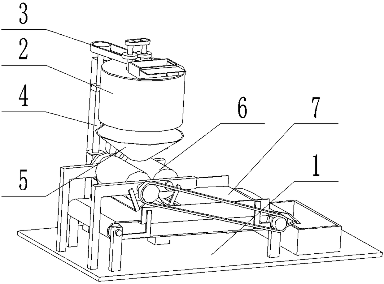
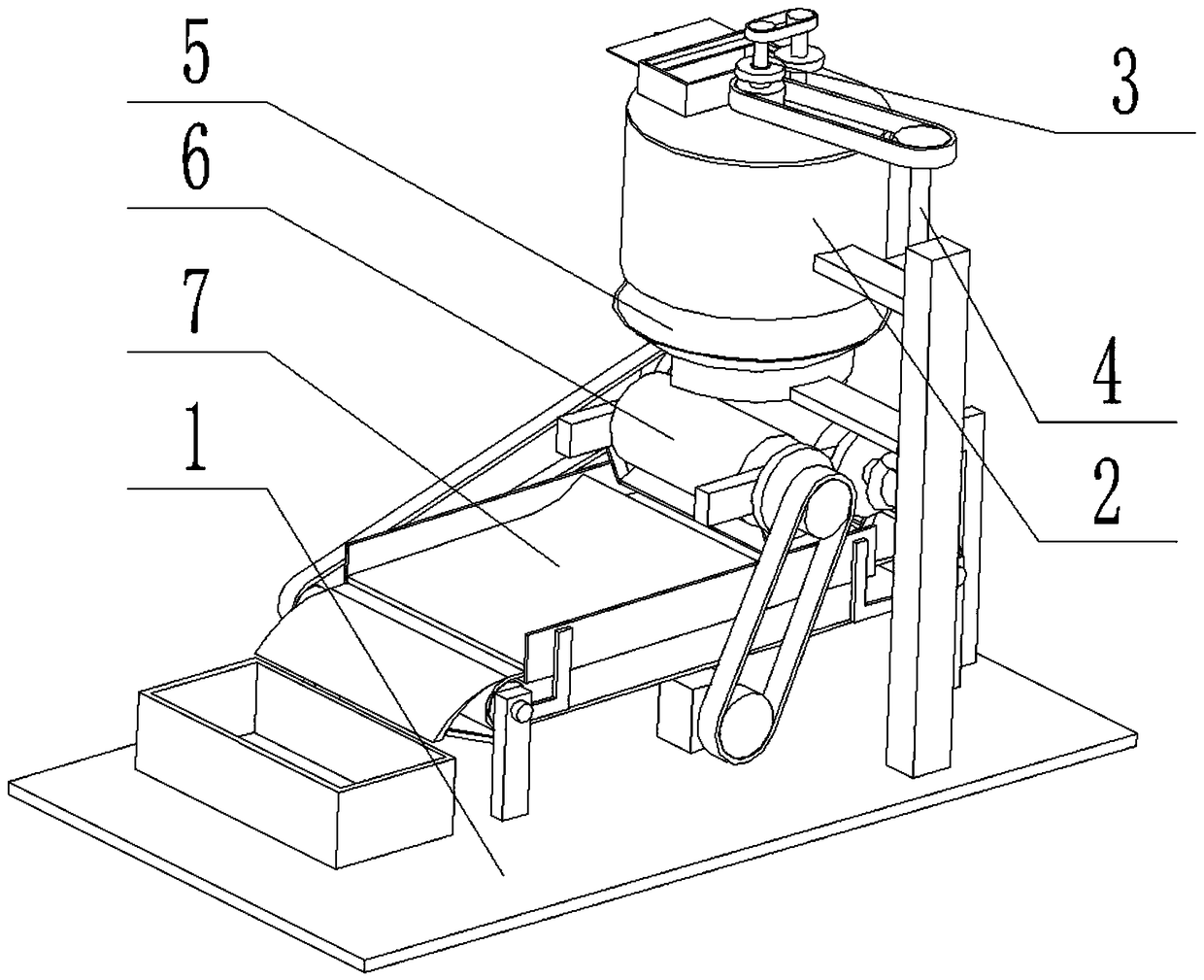
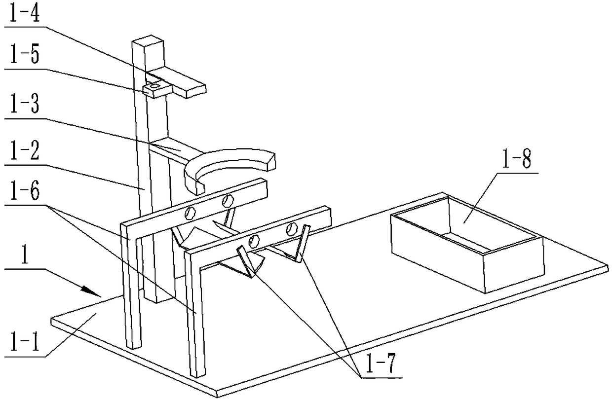
[0033] Such as Figure 1-11 As shown, a ceramic mechanical pulverizer includes a base 1, a grinding cylinder 2, a grinding device 3, a transmission shaft 4, a collection bucket 5 and a grinding drum 6, and the base 1 includes a bottom plate 1-1, a support Rod 1-2, collecting bucket bracket 1-3, grinding tube frame 1-4, transmission shaft frame 1-5 and roller bracket 1-6; pole 1-2 is fixedly connected to one side of bottom plate 1-1; collecting bucket The bracket 1-3 is fixedly connected to the middle end of the support rod 1-2; the grinding cylinder holder 1-4 is fixedly connected to the top of the support rod 1-2; the transmission shaft support 1-5 is fixedly connected to the side of the grinding cylinder holder 1-4 end; there are two roller brackets 1-6, and the two roller brackets 1-6 are symmetrically arranged on both sides of the rear end of the bottom plate 1-1;

[0034] The grinding cylinder 2 includes a grinding cylinder 2-1 and a material inlet 2-2, and the material ...


PUM


Abstract

The invention relates to the field of ceramic powder milling devices, in particular to a ceramic mechanical powder mill. The ceramic mechanical powder mill comprises a base, a grinding cylinder, a grinding device, a transmission shaft, a collecting bucket and milling rollers. The base comprises a bottom plate, a supporting rod, a collecting bucket bracket, a grinding cylinder frame, a transmissionshaft frame and two roller brackets. The supporting rod is fixedly connected to one side of the bottom plate; the collecting bucket bracket is fixedly connected to the middle end of the supporting rod; the grinding cylinder frame is fixedly connected to the top end of the supporting rod; the transmission shaft frame is fixedly connected to the side end of the grinding cylinder frame; the two roller brackets are symmetrically disposed on both sides of the rear end of the bottom plate; the grinding cylinder comprises a grinding cylinder body and a feed inlet, and the feed inlet is connected andcommunicates with one side of the top surface of the grinding cylinder body; and the grinding cylinder body is fixedly connected to the grinding cylinder frame. The ceramic mechanical powder mill canavoid the limitation of single time single-way grinding and the difficulty of evenly grinding ceramic powder by three different ways of grinding, saves processing time, and improves production efficiency.

Description

technical field [0001] The invention relates to the field of ceramic powder milling devices, in particular to a ceramic mechanical powder mill. Background technique [0002] For example, the patent application number is CN201520336033.3, a kind of ceramic mechanical grinding machine, which includes a grinding chassis and a grinding upper plate that cooperates with the grinding chassis, wherein the grinding chassis includes a first bottom plate and is fixedly installed on the Several milling needles on the first bottom plate, the upper plate for grinding powder includes a second bottom plate and a milling column fixedly installed on the second bottom plate to cooperate with the milling needles for grinding. The middle part of the first bottom plate is provided with The shaft hole, the first bottom plate has a bottom surface and a top surface, a circular convex rib protrudes from the bottom surface of the periphery of the shaft hole, and several strip-shaped convex ribs are ar...

Claims


Application Information

Patent Timeline
IPC IPC(8): B02C21/00B02C13/18B02C13/30B02C4/02B02C4/42B02C4/40B02C19/20
CPCB02C4/02B02C4/40B02C4/42B02C13/18B02C13/30B02C19/20B02C21/00
Inventor 郑吉冬
Owner 景德镇市珏昊瓷业有限公司
Why Eureka
Try Eureka