
Staggered-pole rotor of an electric machine

A pole-staggered and rotor technology, applied in electric components, electrical components, electromechanical devices, etc., can solve the problems of reducing harmonics, small pole-staggering angle, and increasing the difficulty of the motor, so as to improve motor performance, reduce management costs, and reduce investment. cost effect

Inactive Publication Date: 2019-01-11
CHONGQING ZOTYE NEW ENERGY AUTOMOBILE TECH RES INST CO LTD
View PDF4 Cites 0 Cited by
  • Summary
  • Abstract
  • Description
  • Claims
  • Application Information

AI Technical Summary

Problems solved by technology

[0002] At present, permanent magnet synchronous motors mainly reduce harmonics and reduce cogging torque through the way of rotor staggered poles. The current way of rotor staggered poles: on the rotating shaft, the rotor positioning key is offset from the magnetic center of the N pole or S pole of the permanent magnet. Move an angle A, then flip the rotor core to realize 2-stage wrong poles, the wrong pole angle is 2A, this scheme can only realize 2-stage rotor core wrong poles, reduce harmonics, and reduce the effect of cogging torque The effect is not obvious, increasing the difficulty of the motor design stage
Due to the limitation of the process, when the number of pole-staggered sections is greater than 2, multiple sets of molds are used to realize the pole-staggered rotors of multiple sections, which increases the mold investment cost and the angle of pole-staggered is small, and the rotor cores of different sections are not easy to identify, which is not conducive to the rotor core. core site management

Method used


Image

  • Staggered-pole rotor of an electric machine
  • Staggered-pole rotor of an electric machine
  • Staggered-pole rotor of an electric machine

Examples


Embodiment Construction

[0024] Below in conjunction with accompanying drawing and embodiment the present invention will be further described:

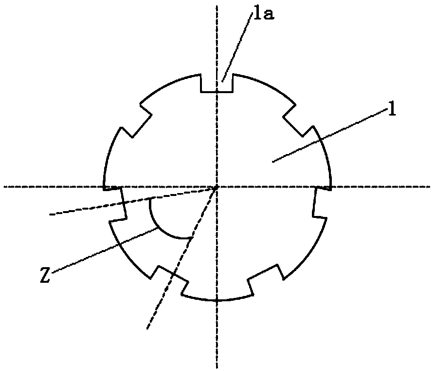
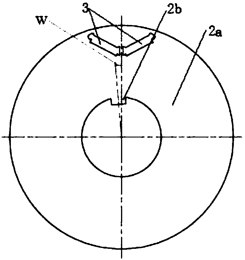
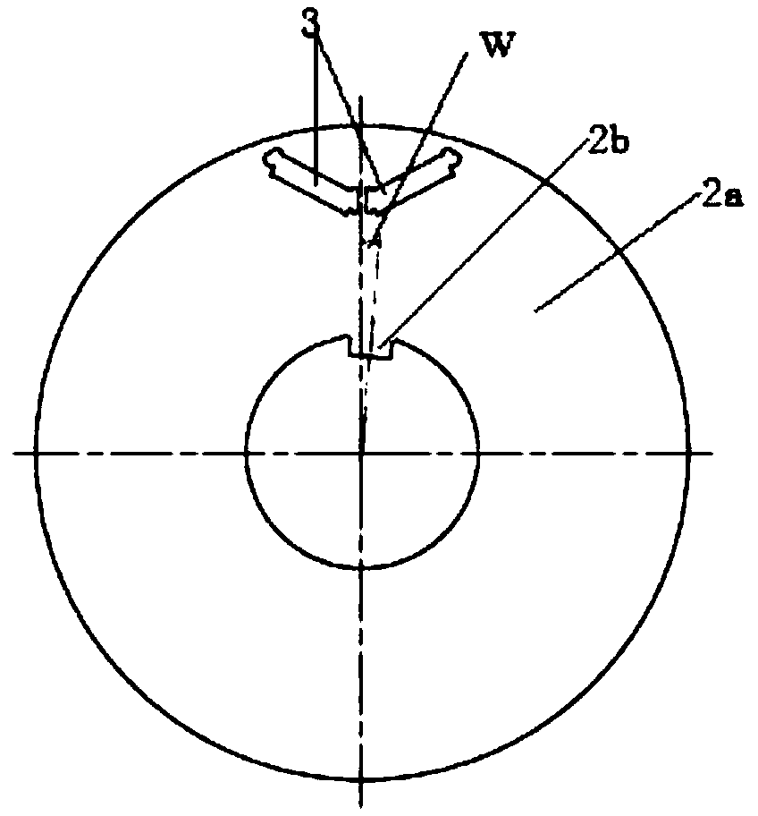
[0025] Such as figure 1 , figure 2 , image 3 , Figure 4 , Figure 5 As shown, the embodiment of the present invention discloses a staggered-pole rotor for a motor, which includes: a rotating shaft 1 whose surface is uniformly and vertically provided with n (n≥2, n is an integer) positioning key grooves 1a concaved inward; an iron core 2 , sleeved on the rotating shaft 1, the iron core 2 is composed of 2n ring-shaped sub-cores 2a, the inner ring of each sub-core 2a is provided with a positioning key 2b protruding inward, and each positioning keyway 1a cooperates with the positioning key 2b of the two overlapping sub-cores.

[0026] In this embodiment, multiple pairs of magnetic pole pairs 3 are arranged between the inner ring and the outer ring of the sub-core and evenly arranged on the sub-core around the inner ring, each pair of magnetic pole pairs 3...


PUM


Abstract

The invention discloses a staggered-pole rotor of an electric machine, which is characterized in that: a rotating shaft is uniformly and vertically provided with n (n>= 2, n is an integer) inward concave positioning key grooves on the surface thereof. The iron core is sleeved on the rotating shaft, the iron core is composed of 2n-segment ring-shaped sub-iron core surfaces, and each inner ring of the sub-iron core is provided with a positioning key protruding inward, wherein each positioning key slot is matched with two overlapping positioning keys of the sub-iron core. Through the motor staggered rotor of the invention, the staggered pole of the multi-segment rotor can be realized by using a set of moulds.

Description

technical field [0001] The invention relates to the technical field of electric motors, in particular to an electric motor with a wrong pole rotor. Background technique [0002] At present, permanent magnet synchronous motors mainly reduce harmonics and reduce cogging torque through the way of rotor staggered poles. The current way of rotor staggered poles: on the rotating shaft, the rotor positioning key is offset from the magnetic center of the N pole or S pole of the permanent magnet. Move an angle A, then flip the rotor core to realize the two-stage wrong pole of the rotor, and the wrong pole angle is 2A. In this scheme, a set of molds can only realize the wrong pole of the two-stage rotor core, reducing harmonics and reducing the cogging torque. The effect is not obvious, which increases the difficulty of the motor design stage. Due to the limitation of the process, when the number of wrong pole segments is greater than 2, multiple sets of molds are used to realize mul...

Claims


Application Information

Patent Timeline
IPC IPC(8): H02K1/24H02K1/27H02K21/14
CPCH02K1/24H02K1/2773H02K21/14
Inventor 江国杰梁刘才彭洪
Owner CHONGQING ZOTYE NEW ENERGY AUTOMOBILE TECH RES INST CO LTD
Learn More