
Non-marker far-field super-resolution microscopic system and method based on non-diffraction super-resolution beam illumination

A microscopic system and super-resolution technology, applied in the field of visible light microscopy, can solve the problems of limited practical application, short depth of focus, and difficulty in further improving the overall resolution of the system, and achieve strong illumination beam penetration, large working distance, The effect of spreading over a long distance

Active Publication Date: 2019-01-11
CHONGQING UNIV
View PDF6 Cites 13 Cited by
  • Summary
  • Abstract
  • Description
  • Claims
  • Application Information

AI Technical Summary

Problems solved by technology

In recent years, there have been a few experimental reports on label-free far-field super-resolution microscopy based on super-diffraction devices. However, the existing non-label far-field super-resolution microscope illumination beam has a short depth of focus and is difficult to penetrate the sample glass slide. , and it is difficult to penetrate thicker samples to achieve super-resolution illumination, which greatly limits its practical application; at the same time, the existing non-marked far-field super-resolution microscope illumination beam has a short focal depth, and it is difficult to penetrate the sample glass slide , which also makes it impossible to use a microscope objective lens with large numerical aperture and high magnification, and cannot reduce the full width at half maximum of the point spread function of the objective lens, so it is difficult to further improve the overall resolution of the system

Method used


Image

  • Non-marker far-field super-resolution microscopic system and method based on non-diffraction super-resolution beam illumination
  • Non-marker far-field super-resolution microscopic system and method based on non-diffraction super-resolution beam illumination
  • Non-marker far-field super-resolution microscopic system and method based on non-diffraction super-resolution beam illumination

Examples


Embodiment Construction

[0027] The technical solution of the present invention will be further described below in conjunction with the accompanying drawings.

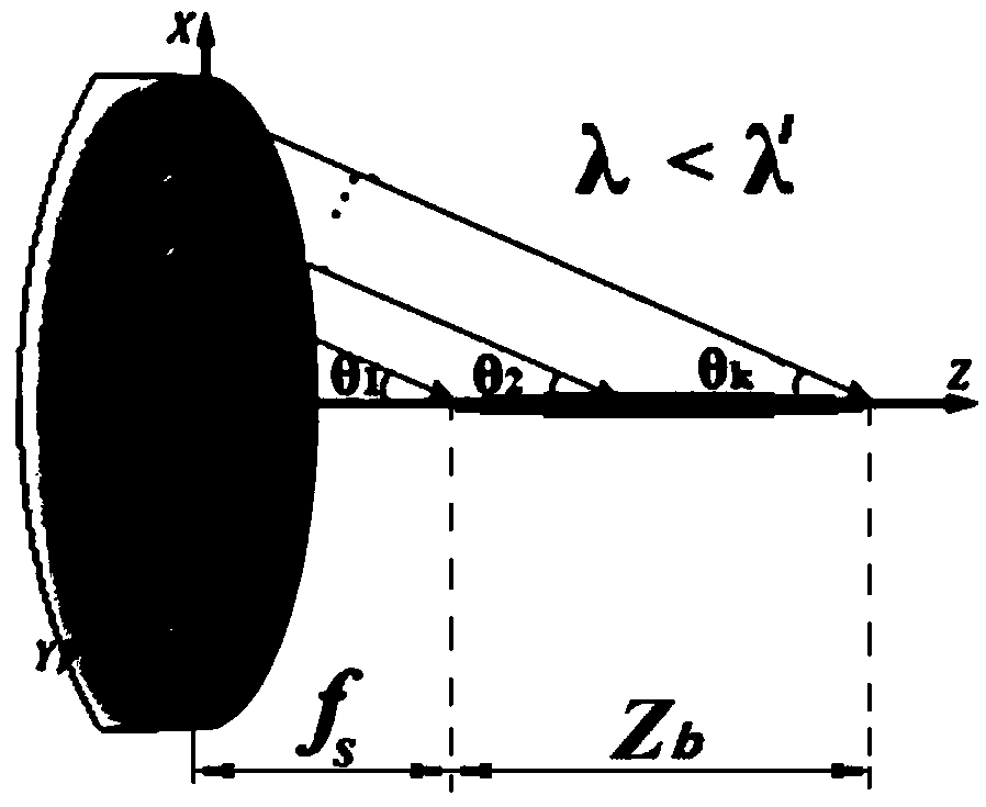
[0028] like figure 1 As shown, the non-marking far-field super-resolution microscopy system based on non-diffraction super-resolution beam illumination proposed by the present invention includes a non-diffraction super-resolution beam illumination module, a sample two-dimensional scanning module, a traditional micro-optical module, and a super-resolution imaging module. module. Its specific structure is as follows:

[0029] The non-diffraction super-resolution beam illumination module is used to generate a non-diffraction super-resolution beam, which includes a laser 1, a fiber coupler 2, an optical fiber 3, a fiber collimator 4, a super-diffraction lens 5, a five-dimensional adjustment mechanism 6, a one-dimensional Nano-displacement piezoelectric stage 7, two-dimensional pitch adjustment mechanism 8 and three-dimensional adjustment mechani...


PUM


Abstract

The invention relates to a non-marking far-field super-resolution microscopic system and method based on non-diffraction super-resolution beam illumination, which comprises a non-diffraction super-resolution beam illumination module, a sample two-dimensional scanning module, a microscopic optical module, and a super-resolution imaging module. The illumination light source adopts the non-diffraction super-resolution beam, and has the advantages that the working distance is large, the illumination beam propagation distance is far, the illumination beam penetration is strong, and the light beam transverse half-height full-width is smaller than the diffraction limit; a confocal mode is adopted to realize the far-field super-resolution imaging system and method without marking; and can realizethe three-dimensional tomographic imaging of the transparent sample, the transverse resolution is smaller than the diffraction limit, and is better than lambada / 5. The method can be applied to non-marking super-resolution microscopic imaging of biological samples and can also be applied to the fields of industrial related super-resolution microscopic detection and the like.

Description

technical field [0001] The invention belongs to the field of visible light microscopy technology, and in particular relates to a non-marking far-field super-resolution microscopy system and method based on non-diffraction super-resolution beam illumination. The system can realize non-marking, super-resolution resolution, Tomography can be applied to detection applications of biological samples, etc. Background technique [0002] The existing microscopy techniques can be roughly divided into two categories: near-field microscopy and far-field microscopy. Near-field microscopy includes microsphere-assisted imaging, near-field scanning microscopy and other methods. Near-field microscopy can achieve super-resolution microscopy imaging, but its working distance is smaller than the working wavelength, which greatly limits its practical application; far-field super-resolution technology, with a large working distance, can overcome the shortcomings of near-field microscopy . Exist...

Claims


Application Information

Patent Timeline
Patent Type & Authority Applications(China)
IPC IPC(8): G02B21/00G02B21/06G02B21/26G02B21/36G02B27/58
CPCG02B21/002G02B21/06G02B21/26G02B21/361G02B27/58
Inventor 陈刚温中泉张智海江雪梁高峰
Owner CHONGQING UNIV
Learn More