Spectrum splicing optical frequency domain reflection-type distributed fiber sensor and signal demodulation method

A distributed optical fiber, optical frequency domain reflection technology, applied in the direction of converting sensor output, using optical devices to transmit sensing components, instruments, etc., can solve the problems of narrow operating temperature range, high vibration reduction requirements, high cost, and improve the environment. The effect of adaptability, reduced requirements, low cost design

Active Publication Date: 2019-01-11
BEIJING INST OF AEROSPACE CONTROL DEVICES
View PDF9 Cites 13 Cited by
  • Summary
  • Abstract
  • Description
  • Claims
  • Application Information

AI Technical Summary

Problems solved by technology

[0005] The technical problem solved by the present invention is: the existing optical frequency domain reflective distributed optical fiber sensor needs to use a narrow linewidth scanning laser without mode hopping in the measurement spectrum range, which has high cost, large volume, narrow working temperature range and vibration reduction. Requires high-level problems; a spectral mosaic optical frequency domain reflective distributed optical fiber sensor and signal demodulation method is proposed, the measured spectral range is divided into N (N ≥ 2) spectral intervals, and the wavelength of the narrow linewidth scanning laser is sequentially Non-mode-hopping wavelength scanning is carried out in N spectral intervals, and the scattered or reflected signal light spectra in each spectral interval are spliced ​​through digital signal processing to obtain the signal optical spectrum within the measured spectral range, and the optical frequency domain reflective distribution is completed Signal demodulation of optical fiber sensor; reduces the requirements of optical frequency domain reflective distributed optical fiber sensor for laser, reduces cost and volume, improves environmental adaptability, and is conducive to engineering promotion and application

Method used


Image

  • Spectrum splicing optical frequency domain reflection-type distributed fiber sensor and signal demodulation method
  • Spectrum splicing optical frequency domain reflection-type distributed fiber sensor and signal demodulation method

Examples


Embodiment Construction

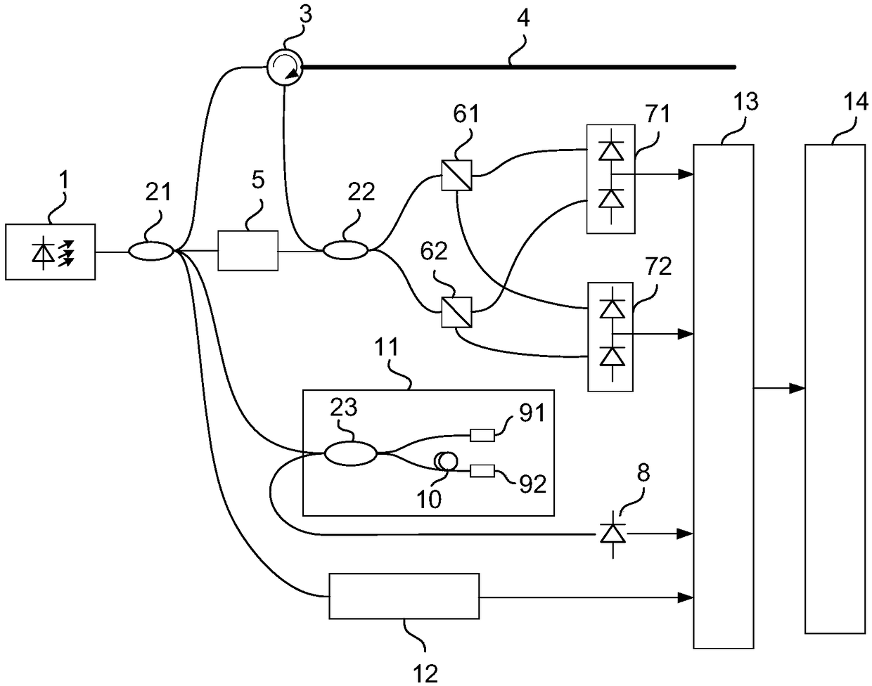
[0035] The present invention discloses a spectral splicing optical frequency domain reflective distributed optical fiber sensor, a specific implementation method is as follows figure 1As shown; the optical frequency domain reflective distributed optical fiber sensor of spectral stitching includes a narrow linewidth scanning laser 1, a first fiber coupler 21, an optical circulator 3, a sensing fiber 4, a polarization controller 5, and a second fiber coupler 22. The first polarizing beam splitter 61, the second polarizing beam splitter 62, the first balanced photodetector 71, the second balanced photodetector 72, the third fiber coupler 23, the first Faraday rotating mirror 91, the second Two Faraday rotating mirrors 92 , time-delay optical fiber 10 , thermally stable etalon 12 , first photodetector 81 , second photodetector 82 , analog-to-digital converter 13 , and signal processing unit 14 .

[0036] The output light of the narrow-linewidth scanning laser 1 is divided into fou...


PUM


Abstract

The present invention discloses a spectrum splicing optical frequency domain reflection-type distributed fiber sensor and a signal demodulation method. The spectrum splicing optical frequency domain reflection-type distributed fiber sensor comprises a narrow linewidth scanning laser, a first optical fiber coupler, an optical circulator, a sensing optical fiber, a polarization control unit, a second optical fiber coupler, a first polarization beam splitter, a second polarization beam splitter, a first balance photoelectric detector, a second balance photoelectric detector, a third optical fibercoupler, a first Faraday rotation reflector, a second Faraday rotation reflector, a reference fiber optic interferometer, a photoelectric detector and a signal collection processing unit. Through spectrum splicing, it is avoided that a laser with a broadband spectrum range and without mode jump is employed to reduce the cost; the laser package and control are simplified to facilitate miniaturization design; and the requirements for the environment temperature and the vibration condition are reduced to facilitate project promotion application.

Description

Technical field [0001] The invention relates to a distributed optical fiber sensor, in particular to a spectral splicing optical frequency domain reflective distributed optical fiber sensor. Background technique [0002] Optical frequency domain reflective distributed optical fiber sensor, through the optical frequency domain reflectometer to measure the backward Rayleigh scattering along the optical fiber and the backward reflection of the fiber grating, can realize distributed measurement or multi-point measurement of optical fiber temperature, strain, vibration, etc. , has the advantages of high spatial resolution, large number of measuring points, and low average cost of a single measuring point, and is widely used in structural monitoring such as aerospace, aviation, and civil engineering. [0003] The time delay between the scattered or reflected signal light at different positions of the optical frequency domain reflective distributed optical fiber sensor and the loca...

Claims


Application Information

Patent Timeline
Patent Type & Authority Applications(China)
IPC IPC(8): G01D5/353
CPCG01D5/35303G01D5/35306
Inventor 唐才杰王学锋贾鲁宁罗明明王明超蓝天
Owner BEIJING INST OF AEROSPACE CONTROL DEVICES
Why Eureka
Try Eureka