Absorbable pulling rivet

A technology of pulling rivets and rivets, which is applied in the direction of rivets, screws, threaded fasteners, etc., and can solve problems such as inconsistent nail bodies, offset misalignment, and poor fixation stability, so as to avoid offset misalignment, ensure stability, and delay sliding Effect

Pending Publication Date: 2019-01-11
CHANGZHOU WASTON MEDICAL APPLIANCE CO LTD
View PDF6 Cites 1 Cited by
  • Summary
  • Abstract
  • Description
  • Claims
  • Application Information

AI Technical Summary

Problems solved by technology

[0004] The technical problem to be solved by the present invention is: in order to solve the problem that the sliding direction of the rivet is not consistent with the direction of the pulling force when pulling the rivet, the rivet body is displaced and misplaced, and the fixation stability is poor. The present invention provides an absorbable rivet. Place the bone plate at the fracture site and punch a hole into the bone, insert the nail body into the riveting tube from one side of the expansion groove, insert the side of the expansion groove of the riveting tube into the hole, and use a general riveting gun The expansion body is pulled into the riveting tube, and the riveting tube expands and squeezes the bone tissue outward after being squeezed by the expansion body to fix it. When the riveting gun pulls the nail body, the nail body is close to the inner wall of the riveting tube, and the riveting tube The inner wall of the inner wall plays a guiding role for the nail body, so that the pulling force on the nail body is consistent with the sliding direction of the nail body, avoiding the offset and dislocation of the nail body, and at the same time pulling the nail body and the inside of the rivet tube to generate friction to delay the sliding of the nail body and improve It ensures the controllability of the nail body pulling and ensures the stability of the riveting work

Method used


Image

  • Absorbable pulling rivet
  • Absorbable pulling rivet
  • Absorbable pulling rivet

Examples


Embodiment Construction

[0029] The present invention is described in further detail now in conjunction with accompanying drawing. These drawings are all simplified schematic diagrams, which only illustrate the basic structure of the present invention in a schematic manner, so they only show the configurations related to the present invention.

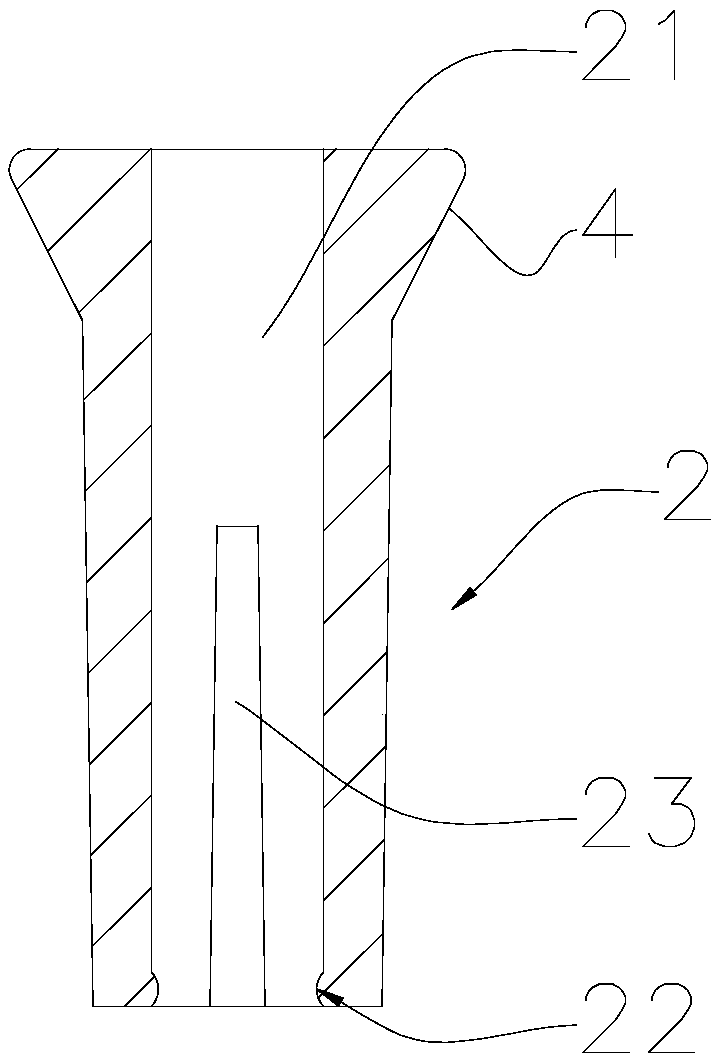
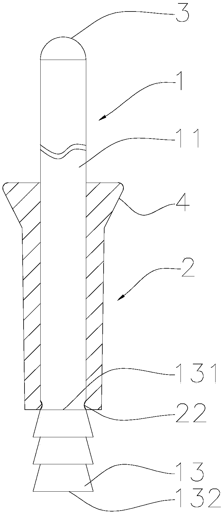
[0030] Such as Figure 1-3 As shown, the present invention provides an absorbable blind rivet 1, comprising a rivet 1 and a rivet tube 2,

[0031] The rivet tube 2 has a hollow channel 21 for the rivet 1 to pass through, the inner side wall of the rivet tube 2 has an annular protrusion 22, and the side wall of the rivet tube 2 is provided with a number of expansion grooves 23 for the expansion of the rivet tube 2;

[0032] The rivet 1 includes a nail body 11 and an expansion body. The diameter of the nail body 11 is the same as that of the hollow channel 21 of the rivet tube 2. The maximum diameter of the expansion body is larger than the diameter of the nail...


PUM


Abstract

The invention relates to the technical field of pulling rivets, in particular to an absorbable pulling rivet. The absorbable pulling rivet comprises a rivet and a riveting tube; the riveting tube is provided with a hollow passage convenient for the rivet to pass through; the inner side wall of the riveting tube is provided with an annular protrusion; a plurality of expansion slots convenient for the riveting tube to expand are formed in the side wall of the riveting tube; the rivet comprises a rivet body and an expansion body; the diameter of the rivet body is equal to that of the hollow passage; the maximum diameter of the expansion body is greater than the diameter of the rivet body; an annular groove matched with the annular protrusion in shape is formed in the joint of the rivet body and the expansion body; the rivet body of the rivet passes through the riveting tube and makes the annular protrusion clamped into the annular groove; and the rivet body is exposed outside the rivetingtube. In a process that the rivet body is pulled by a pulling riveter, the rivet body clings to the inner wall of the riveting tube; guide action is exerted on the rivet body by the inner wall of theriveting tube, so that a pull on the rivet body is same as a sliding direction of the rivet body, and the rivet body is prevented from skewing and deflecting.

Description

technical field [0001] The invention relates to the technical field of blind rivets, in particular to an absorbable blind rivet. Background technique [0002] Modern medical orthopedic implants are generally fixed with screws made of metal materials such as titanium alloy and stainless steel with high elastic modulus, or with screws made of poly-L-lactic acid and polyglycolic acid, mainly through thread and contact. Due to the small joint surface and the absorption effect of the bone under stress, the operation of threaded nails is time-consuming and difficult, which often leads to loosening or falling off of the internal fixation of fractures, especially in cancellous bone. And screws made of metal materials are not absorbed and need to be taken out by surgery again or remain in the body as foreign bodies for life. [0003] Chinese patent CN 101502440A discloses an absorbable expandable bone rivet. One end of the tubular rivet is provided with an annular cap, and the other...

Claims


Application Information

Patent Timeline
Patent Type & Authority Applications(China)
IPC IPC(8): F16B19/10
CPCF16B19/10F16B2019/1009F16B19/1045
Inventor 周维吴伟敏胡仁民
Owner CHANGZHOU WASTON MEDICAL APPLIANCE CO LTD
Why Eureka
Try Eureka