
Fast die erecting device for closed wall and construction method

A construction method and airtight wall technology, applied in mining equipment, earth square drilling, mining equipment, etc., can solve problems such as easy cracking and air leakage, reduce construction efficiency, and increase airtight cost, so as to achieve easy promotion, improve airtight efficiency, and reduce airtightness cost effect

Pending Publication Date: 2019-01-11
徐州和盛矿业科技有限公司
View PDF2 Cites 1 Cited by
  • Summary
  • Abstract
  • Description
  • Claims
  • Application Information

AI Technical Summary

Problems solved by technology

The main problems currently existing in various types of airtight walls in coal mines in my country are: ① The materials used to construct the airtight walls have poor performance. The masonry materials and concrete used are rigid materials, which are very easy to crack and leak air under the action of dynamic pressure.
② The construction technology is backward, the construction period is long, and the efficiency is low, and the construction is mainly done by hand
③A large amount of material is used for the airtight wall, which increases the auxiliary transportation volume of the mine
Although this method ensures the flatness of the wall surface, it needs to construct anchor rods on the side and roof when the formwork is erected, which consumes extra manpower and material resources and reduces the construction efficiency.
In some airtight projects, single hydraulic props are used to formwork with steel mesh. This method is fast in construction, but the inner monomer cannot be recycled after airtight, which increases the airtight cost

Method used


Image

  • Fast die erecting device for closed wall and construction method
  • Fast die erecting device for closed wall and construction method
  • Fast die erecting device for closed wall and construction method

Examples


Embodiment

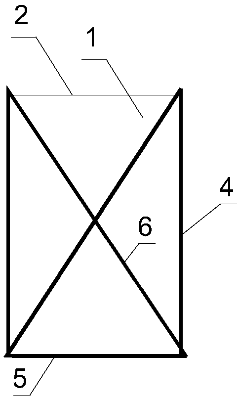
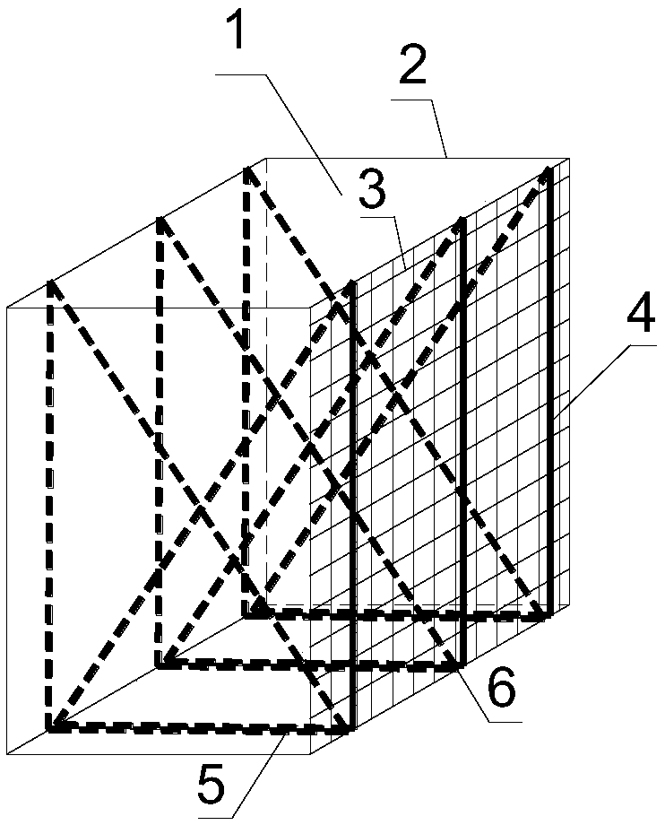
[0025] refer to Figure 1-4 , a closed wall rapid formwork device, comprising a closed wall wall 1, the rapid formwork device is composed of a vertical bar 4, a horizontal bar 5, an oblique bar 6, the vertical bar 4, horizontal bar 5, The oblique rods 6 are connected in a hinged manner, the vertical rods 4 are vertically placed on the bottom plate of the airtight wall body 1, the horizontal rods 5 are fixed on the bottom plate of the airtight wall body 1, and the oblique rods 6 pass through The flexible airtight bag 2 is connected with the horizontal bar 5 and the vertical bar 6 to form a tripod structure, and a steel mesh 3 is placed between the vertical bar 4 and the flexible airtight bag 2 .

[0026] In this embodiment, the specifications of the airtight wall body 1 are set to be 4000 mm wide x 3000 mm high x 1500 mm thick.

[0027] ①According to the section size of the roadway, use φ50×5mm steel pipe to process 6 vertical rods 4 with a length of 3000mm, horizontal rods 5 ...


PUM


Abstract

The invention discloses a fast die erecting device for a closed wall. A closed wall body is included. The fast die erecting device is composed of a vertical rod, a horizontal rod and an oblique rod, wherein the vertical rod, the horizontal rod and the oblique rod are connected with each other in a hinge manner, the vertical rod is vertically placed on a bottom plate of the closed wall body, the horizontal rod is fixed on the bottom plate of the closed wall body, the oblique rod penetrates through a flexible closed bag and is connected with the horizontal rod and the vertical rod to form a tripod structure, and a steel mesh is placed between the vertical rod and the flexible closed bag. The construction method comprises steps that S1, the vertical rod, the horizontal rod and the oblique rodfor steel pipe processing are respectively prepared, the vertical rod, the horizontal rod and the oblique rod are hinged through pins, and the air-cylinder coated cloth is processed into the flexibleclosed bag. The fast die erecting device is advantaged in that fast die erecting in a closed state is realized, a problem that a side vertical mold individual body can not be recycled in the closed wall is solved, enclosure cost is reduced, and roadway enclosure efficiency is improved.

Description

technical field [0001] The invention relates to the technical field of coal mine safety, in particular to a fast formwork device and construction method for an airtight wall. Background technique [0002] In coal mine production, in order to prevent the spontaneous combustion of coal seams, the diffusion of harmful gases or the impact of gas explosions on safe production, airtight walls are often built to seal off scrapped goafs, tailgates and connecting lanes in a timely manner, so as to prevent spontaneous combustion areas, harmful gas sources or gas accumulations. The area is isolated, which is crucial to the safe production of the mine. The main problems currently existing in various types of airtight walls in coal mines in my country are: ① The materials used to construct the airtight walls have poor performance. The masonry materials and concrete used are rigid materials, which are very easy to crack and leak air under the action of dynamic pressure. ② The constructio...

Claims


Application Information

Patent Timeline
Patent Type & Authority Applications(China)
IPC IPC(8): E21F17/103
CPCE21F17/103
Inventor 何向宁赵地杰陈勇冯俊杰
Owner 徐州和盛矿业科技有限公司
Learn More