
Electric tricycle

A technology for electric tricycles and front wheels, applied in the field of electric vehicles, can solve problems such as wheel slippage, achieve the effects of reducing slippage, avoiding wear problems, and improving adaptability

Active Publication Date: 2019-01-11
XUZHOU DEGAO ELECTRIC VEHICLE TECH CO LTD
View PDF6 Cites 2 Cited by
  • Summary
  • Abstract
  • Description
  • Claims
  • Application Information

AI Technical Summary

Problems solved by technology

[0003] In view of the above-mentioned technical deficiencies, the purpose of the present invention is to provide an electric tricycle, aiming at the defect that the front wheels generally adopt disc brakes in the prior art and there is locking, so as to reduce the risk of the front wheels being directly locked when the brakes are moving forward. wheel slipping

Method used


Image

  • Electric tricycle
  • Electric tricycle
  • Electric tricycle

Examples


Embodiment 1

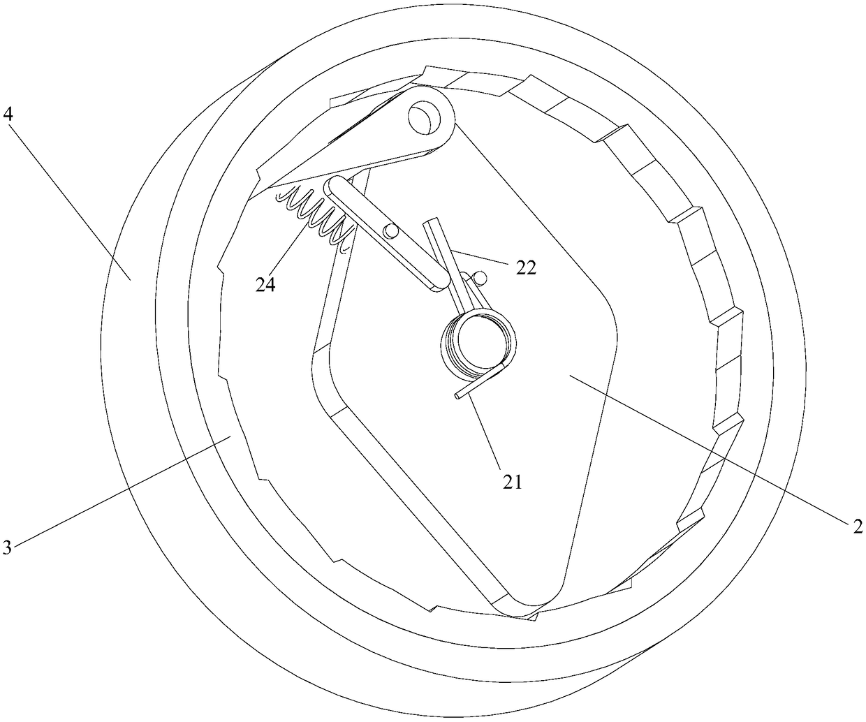
[0019] Embodiment 1: as Figure 1 to Figure 4 Shown, a kind of electric tricycle, comprises vehicle underframe and three wheels that are installed on described vehicle underframe, and described wheel comprises a front wheel and two rear wheels, and brake unit is arranged on the described front wheel, so The brake unit includes a main shaft 1, a chuck 3 rotatably arranged on the main shaft 1, and a buffer disc 4 rotatably arranged on the main shaft 1, and the buffer disc 4 is fixedly arranged with the front wheel, so The main shaft 1 is installed on the undercarriage, the main shaft 1 is fixed with a rhombus block 2, one end of the rhombic block 2 is provided with a rotatable block 25, and the corresponding chuck 3 is provided with a A number of slots 31 are evenly distributed along the circumferential direction, and a cylindrical spring 24 is fixedly arranged between the block 25 and the diamond-shaped block 2, and the cylindrical spring 24 is in a stretched state. A link mec...

Embodiment 2

[0025] Embodiment 2: On the basis of Embodiment 1, the rotation center of the second lever 23 can be placed on the side away from the main shaft 1, and a part of labor can be realized by using the difference in the moment arm.

Embodiment 3

[0026] Embodiment 3: On the basis of Embodiment 1 or Embodiment 2, the elasticity and the number of turns of the vortex spring 5 can be further set accordingly, and the shrinkage of the vortex spring 5 and the number of turns can be realized. The adjustment of the resistance generated by the wheels, and then control the deceleration time of the wheels and the braking distance, the application does not limit the specific elastic force and the number of turns of the spiral spring 5 here.

[0027] When not braking, the brake unit is in the initial state, that is, the vortex spring 5 does not shrink, the block 25 is in the second position, and the front wheel can rotate freely; when in use, the main shaft 1 is installed on the vehicle chassis, and the buffer disc 4 is connected to the front wheel. Fixed, the front wheel drives the buffer disc 4 to rotate together, and simultaneously through the vortex spring 5, the buffer disc 4 drives the chuck 3 to rotate ( image 3The middle ar...


PUM


Abstract

The invention discloses an electric tricycle, comprising chassis wheels, wherein the wheels comprise a front wheel and two rear wheels; the front wheel is provided with a brake unit; the brake unit comprises a main shaft, a chuck and a buffer disk; the main shaft is provided with a diamond block and a connecting rod mechanism; the diamond block is provided with a chuck; the chuck is provided witha chuck slot; a cylindrical spring is arranged between the chuck block and the diamond block; and a scroll spring is arranged between the buffer disk and the chuck. The present invention utilizes therelative rotating between the buffer disk and the chuck, so that upon brake, The wheel can produce a certain brake cushioning distance, thereby avoiding the defect that the disc brake locks the wheelat the instant of braking, thereby reducing the risk of wheel skidding, changing the traditional friction braking mode, and avoiding the wear problem after the transmission friction braking mode is used for a long time.

Description

technical field [0001] The invention relates to the technical field of electric vehicles, in particular to an electric tricycle. Background technique [0002] Along with the continuous popularization of electric vehicles, the use range and quantity of electric tricycles also gradually increase. For vehicles, its braking is the top priority, and the quality of the brakes determines personal safety. There are many kinds of brake units used, and the common disc brakes are installed on the front wheels of electric vehicles, which realize the braking function by locking the brake discs with hydraulic oil. The disc brakes configured on ordinary electric vehicles are not It may be that the disc brakes on a car have an anti-lock function, so the front wheel of an ordinary electric vehicle adopts this disc brake and there is a lock phenomenon, which causes slippage during braking and poses a threat to personnel safety. Contents of the invention [0003] In view of the above-mentio...

Claims


Application Information

Patent Timeline
Patent Type & Authority Applications(China)
IPC IPC(8): B62L1/00B62K5/027
CPCB62K5/027B62L1/00
Inventor 张厚华
Owner XUZHOU DEGAO ELECTRIC VEHICLE TECH CO LTD
Learn More