
Multifunctional inspection robot

An inspection robot and multi-functional technology, applied in the field of robotics, can solve the problems that the detection device cannot adapt to the inspected equipment, and the efficiency and accuracy of the inspected equipment are low, so as to ensure stability, improve efficiency and accuracy, and improve The effect of precision

Inactive Publication Date: 2019-01-11
GUANGDONG POWER GRID CO LTD +2
View PDF13 Cites 6 Cited by
  • Summary
  • Abstract
  • Description
  • Claims
  • Application Information

AI Technical Summary

Problems solved by technology

However, due to the complex location of the inspected equipment, the detection device on the robot cannot adapt to the inspected equipment with variable locations, resulting in low efficiency and accuracy for the robot to detect the inspected equipment

Method used


Image

  • Multifunctional inspection robot
  • Multifunctional inspection robot
  • Multifunctional inspection robot

Examples


Embodiment 1

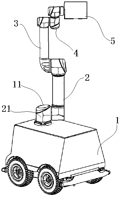
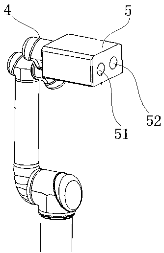
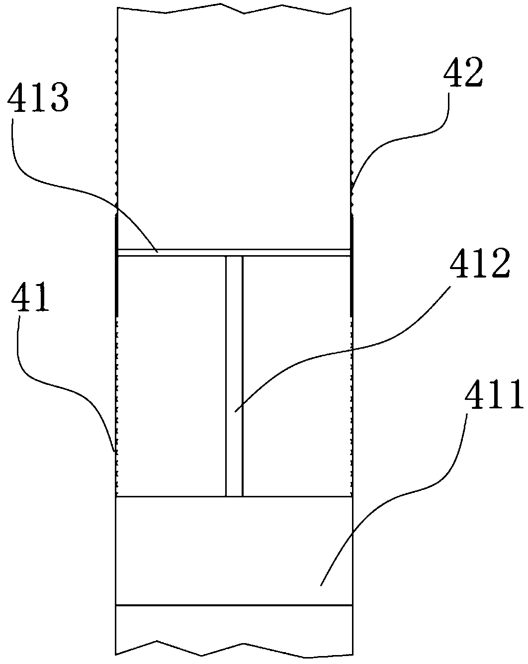
[0024] Such as figure 1 As shown, the present invention provides a multifunctional inspection robot, including a car body 1 and a mechanical arm arranged on the car body 1, the mechanical arm is provided with a first mechanical arm 2 connected to the car body 1, and the first mechanical arm A connecting piece 21 is provided on the arm 2 , and the connecting piece 21 can be connected with the connecting shaft 11 provided on the vehicle body 1 . The connection between the connecting piece 21 and the connecting shaft 11 adopts a rotational connection, and the rotating connection adopts a bearing connection, which can realize the relative rotation between the connecting piece 21 and the connecting shaft 11, and realize the relative rotation of the first mechanical arm 2 relative to the connecting shaft 11. The rotation of car body 1. In this embodiment, the mechanical arm is provided with a second mechanical arm 3 that is rotationally connected to the first mechanical arm 2, and ...

Embodiment 2

[0029] This embodiment is similar to Embodiment 1, the difference is that in this embodiment, the mechanical device is provided with several sections, and the several sections of mechanical arms are connected to each other by means of rotational connection. The flexible adjustment of the position of the detector 5 is realized by mutual rotation of several mechanical arms.

[0030] In this embodiment, the car body 1 is provided with a rolling device, and the rolling device is a four-wheel mechanism, which can effectively drive the robot to move and improve the efficiency and accuracy of the robot's inspection.

Embodiment 3

[0032] This embodiment is similar to Embodiment 2, the difference is that in this embodiment, a clamping device is provided between the rotating arm 42 and the detector 5, and the detector 5 can be removed through the clamping device, and at the same time The device enables the mounting of other tools to the swivel arm 42, extending the functionality of the robot.


PUM


Abstract

The invention relates to the technical field of robots, in particular to a multifunctional inspection robot. The multifunctional inspection robot comprises a car body and a mechanical arm, wherein themechanical arm is equipped with a first mechanical arm connected with the car body; one end, connected with the car body, of the first mechanical arm is equipped with a connector; the connector is rotatably connected with a connecting shaft of the car body; the first mechanical arm is rotatably connected with a second mechanical arm; the second mechanical arm is rotatably connected with a third mechanical arm; the third mechanical arm is equipped with a fixed arm and a rotary arm; the fixed arm is rotatably connected with the second mechanical arm; the fixed arm is rotatably connected with the rotary arm; the rotary arm can rotate relative to the fixed arm under action of a drive device of the third mechanical arm; one end of the rotary arm is equipped with a detector; and the detector isequipped with a thermal imaging device and an image pick-up device. The multifunctional inspection robot can effectively realize detection on detected equipment, can be suitable for detected equipment at different heights and different positions, improves adaptation in a using process of the robot, and improves precision in a detecting process of the robot.

Description

technical field [0001] The present invention relates to the technical field of robots, and more specifically, to a multifunctional inspection robot. Background technique [0002] In recent years, with the development of the robot industry, security inspection robots have emerged in various fields such as large factories, workshops, and substations. The emergence of the inspection robot system saves a lot of manpower, material resources, and financial resources. Especially for inspections in high-risk places, robots have become the best solution. In the prior art, robots have been able to perform more effective patrol inspections on the inspected equipment. However, due to the complex location of the inspected equipment, the detection device provided on the robot cannot adapt to the inspected equipment with variable locations, resulting in low efficiency and accuracy in detecting the inspected equipment by the robot. Contents of the invention [0003] In order to overcome...

Claims


Application Information

Patent Timeline
IPC IPC(8): B25J5/00
CPCB25J5/007
Inventor 马承志胡泰杨玺樊波魏达郭素梅徐平赖奎桂盛青陈仕升唐星宇谭大作李文辉鲜开义周仁彬
Owner GUANGDONG POWER GRID CO LTD
Learn More