Divided vertical sinter cooler and sinter cooling method

A cooling machine and sintering ore technology, which is applied in the field of sintering ore cooling machine and sintering ore cooling, subdivided vertical sintering ore cooling machine and sintering ore cooling, which can solve flue gas parameter fluctuations, poor heat transfer effect and reduce waste heat boiler Thermal efficiency value and other issues

Pending Publication Date: 2019-01-08
ZHONGYE-CHANGTIAN INT ENG CO LTD
View PDF9 Cites 2 Cited by
  • Summary
  • Abstract
  • Description
  • Claims
  • Application Information

AI Technical Summary

Problems solved by technology

No matter which way you choose, it will cause a high investment cost, which is not cost-effective in terms of economic indicators;
[0007] 2) The open circulation of the air flow leads to low utilization rate of waste heat and pollutes the environment: Since the air flow of the "extraction type longitudinal plate cooling technology" is an open circuit circulation, the air from the waste heat boiler is directly exhausted and not recycled, resulting in more than 100 Sensible heat of the air at a high temperature is wasted, and the discharged air contains a large amount of small particles of dust, causing a certain degree of particulate matter pollution to the atmosphere;
[0008] 3) The material at the feed inlet is severely worn: due to the "ventilated longitudinal plate cooling technology" that sets the material seal at the feed chute, there will be a friction distance between the lower part of the material seal and the upper layer of the material surface in the plate cooler box
At this time, the sintered material is easily pulverized and broken when it is rubbed under the double-layer harsh working conditions of high temperature and upper material column extrusion, thereby reducing the yield of the sintering machine;
[0009] 4) The environmental pollution is serious: due to the negative pressure ventilation technology adopted in the "ventilation type longitudinal plate cooling technology", it does not set a sealing cover device at the lower tray of the box body
In this way, when the sinter is scraped off by the scraper device, it is easy to cause a large number of fine particles and dust to splash
And once the exhaust fan breaks down and repaired, all the material dust pushed around the plate cooler will enter the atmosphere, causing extremely bad influence on the operating environment next to the machine
[0010] 5) The thermal efficiency of the waste heat boiler has not reached the highest: because the "ventilated longitudinal plate cooling technology" does not accurately classify the air passing through the material layer according to the air temperature, but mixes it all into the waste heat boiler, so when the outlet air temperature of the low temperature section is too low , it will inevitably lower the temperature of the air entering the waste heat boiler, thereby reducing the thermal efficiency value of the waste heat boiler
The sinter coolers of the prior art generally have the following problems: 1. Serious air leakage and high power consumption
The three cooling methods are to place the sinter on the trolley, and cool the sinter by blowing or drawing air. The seal between the trolley and the bellows is difficult to solve. Generally, the air leakage rate is more than 20%, or even as high as 50%. Increased cooling power consumption; 2. Insufficient heat exchange
Cross-flow heat exchange between sinter and cooling air in belt cooler or ring cooler, the heat transfer effect is poor; the accumulation height of sinter material layer is low, the heat exchange time between sinter and cooling air is short, and the heat exchange is insufficient; 3. Waste heat utilization efficiency is low
Because the two ends of the cooler cannot be sealed, a large amount of wild wind infiltrates. Since the wild wind does not pass through the sintered material layer, it not only increases the power and power consumption of the fan, but also greatly reduces the temperature of the flue gas after heat exchange; the existing In the sintering machine waste heat power generation system, the air is generally taken from the high-temperature sections I and II of the belt cooler or ring cooler. The temperature difference between the sintering ore and the cooling air heat exchange end is large, the flue gas temperature is low, and the loss of working capacity is large. The waste heat utilization rate is low; 4. The waste heat parameters fluctuate greatly
The output, temperature, and composition of sinter fluctuate greatly during the production process, which leads to large fluctuations in flue gas parameters after heat exchange, which has a great impact on waste heat utilization; 5. Whether it is a belt cooler or an annular cooler , are large in size, high in investment, high in energy consumption, heavy in equipment maintenance workload, and long in the project investment recovery cycle

Method used


Image

  • Divided vertical sinter cooler and sinter cooling method
  • Divided vertical sinter cooler and sinter cooling method
  • Divided vertical sinter cooler and sinter cooling method

Examples


Embodiment approach

[0130] According to the first embodiment provided by the present invention, a compartmentalized vertical sinter cooler is provided.

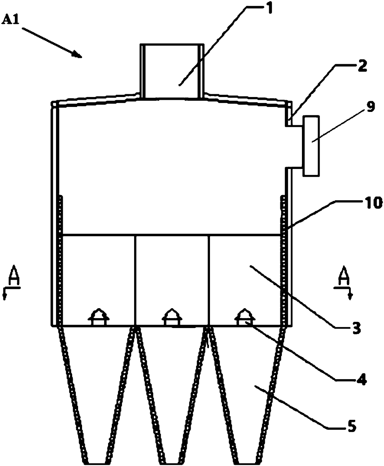
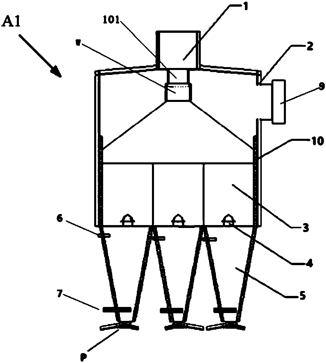
[0131] A compartmentalized vertical sinter cooler, the compartmentalized vertical cooler A1 includes a silo 1 , a tower body 2 , a compartmental frame 3 , an air inlet device 4 , a discharge cone 5 and a hot air outlet 9 . Wherein: the feed bin 1 is set directly above the tower body 2 . The grid frame 3 is arranged in the tower body 2 and is located at the lower part of the tower body 2 . The air inlet device 4 is arranged at the bottom of the tower body 2 . The discharge cone 5 is arranged below the tower body 2 . The grid frame 3 divides the inner lower part of the tower body 2 into a plurality of independent spaces. The hot air outlet 9 is arranged on the top or top of the tower body 2 .

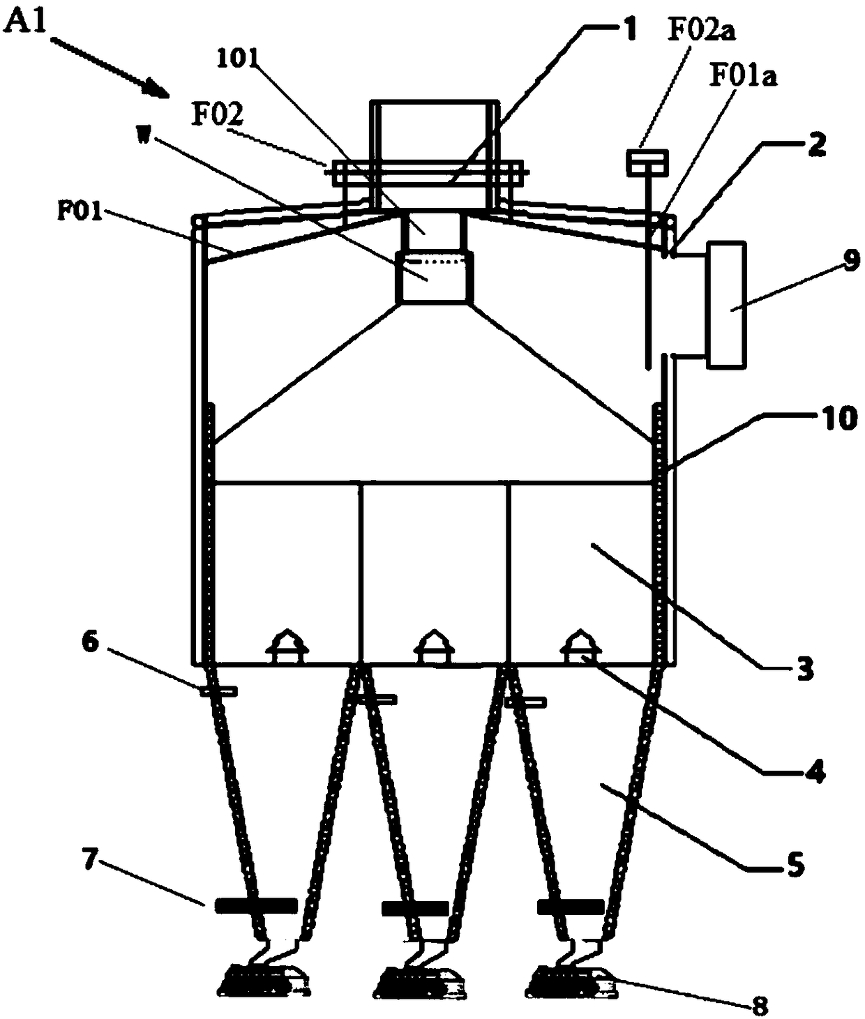
[0132] Preferably, the subdivided vertical cooler A1 also includes a material height adjusting device W. The end of the feed bin 1 is provided with a ...

Embodiment 1

[0197] The height of the tower body 2 is 9 meters, and the length and width of the tower body 2 are 14 meters. The height of the discharge cone 5 is 7 meters. The discharge device P is a double-layer vibrating feeder. Above the interior of the tower body 2, a first ring-shaped radiant heat recovery device F01 is formed by assembling a plurality of ring-shaped hollow plates.

[0198] The diameter of the hood M is 2.5 meters.

[0199] The daily processing capacity of sinter is 8600 tons / day. The temperature of the sintered ore before entering the silo 1 is about 700°C, and the temperature of the hot air at the hot air outlet 9 reaches about 500°C. The recovered heat is used to generate electricity, and the power generation is about 36 kWh.

[0200] Compared with the prior art annular cooler, the advantages are: high power generation, low air leakage rate, small dust emission, simple and reliable equipment, and because of better sealing, the technology of the present inventio...

Embodiment 2

[0203] Repeat embodiment 1, just further be provided with the second radiant heat recoverer F01a at the front end of hot air outlet 9; Adopt shell and tube type heat exchanger, as Figure 18 shown.


PUM


Abstract

Provided is a divided vertical sinter cooler. The divided vertical sinter cooler (A1) comprises a material bin (1), a tower (2), a dividing frame (3), an air feeding device (4), a discharging conicalhopper (5) and a hot air outlet (9), wherein the material bin (1) is arranged over the tower (2); the dividing frame (3) is arranged inside the tower (2) and located on the lower portion of the tower(2); the air feeding device (4) is arranged at the bottom of the tower (2); the discharging conical hopper (5) is arranged below the tower (2); the dividing frame (3) divides the lower part of the interior of the tower (2) into a plurality of independent spaces; and the hot air outlet (9) is arranged on the upper portion or the top of the tower (2). The interior of the tower of the vertical sintercooler is divided into a plurality of areas, the air flow and material flow uniformity is ensured, and the waste heat recovery rate is greatly improved through countercurrent heat exchange.

Description

technical field [0001] The invention relates to a sinter cooler and a sinter cooling method, in particular to a compartmentalized vertical sinter cooler and a sinter cooling method, belonging to the fields of ironmaking and environmental protection. Background technique [0002] In the modern sintering process, "cooling" is one of the most critical processes. After the sintered ore has been roasted by the sintering machine, it has formed a high-temperature finished ore. How can it be protectively cooled without affecting its quality and yield, so that it can be sent to the finished product ore bin through a belt conveyor, and at the same time The perfect recovery and utilization of the sensible heat energy it carries has always been a problem that technicians in the industry have been constantly studying. Since the 1960s, the cooling process of sinter has been developed rapidly, which is mainly divided into three categories: belt cooling, ring cooling and disk cooling. In ...

Claims


Application Information

Patent Timeline
Patent Type & Authority Applications(China)
IPC IPC(8): F27D15/02
CPCF27D15/0286
Inventor 温荣耀贺新华张震
Owner ZHONGYE-CHANGTIAN INT ENG CO LTD
Why Eureka
Try Eureka