Turntable structure with built-in scraper

A mud scraper and turntable technology, applied in the direction of cleaning equipment, rotary drilling, rotary drilling rigs, etc., to achieve the effects of highlighting substantive features, improving drilling safety, and excellent mud scraping effect

Inactive Publication Date: 2019-01-08
四川川油工程技术勘察设计有限公司
View PDF0 Cites 1 Cited by
  • Summary
  • Abstract
  • Description
  • Claims
  • Application Information

AI Technical Summary

Problems solved by technology

[0003] The purpose of the present invention is to provide a turntable structure with a built-in mud scraper to solve the problem in the prior art that two drillers are required to completely scrape mud around the surface of the drill pipe during the tripping process, so as to reduce manpower consumption, The purpose of automatic mud scraping

Method used


Image

  • Turntable structure with built-in scraper
  • Turntable structure with built-in scraper
  • Turntable structure with built-in scraper

Examples


Embodiment 1

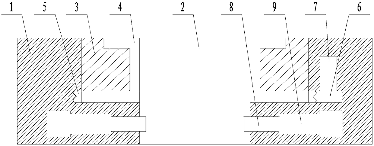
[0022] Such as figure 1 and figure 2 A turntable structure with a built-in mud scraper is shown, including a base body 1, a wellhead passage 2 passing through the base body 1, an annular rotating part 3 capable of rotating around the wellhead passage 2, and a bushing 4 matching the annular rotating part 3 , the annular rotating member 3 is connected to the annular turntable 4, the annular turntable 4 is located inside the base body 1, and the axis of the annular turntable 4 is collinear with the axis of the wellhead channel 2, and the outer edge of the annular turntable 4 is fixed along the circumferential direction. A ring rack 5, a gear 6 and a rotary drive device 7 are arranged in the base body 1, the gear 6 is meshed with the rack 5, and the rotary drive device 7 drives the gear 6 to rotate; the annular turntable 4 There are two mud scrapers 8 symmetrically distributed along the axis of the wellhead passage 2 below the bottom of the wellhead channel 2. The sheets 8 are ...

Embodiment 2

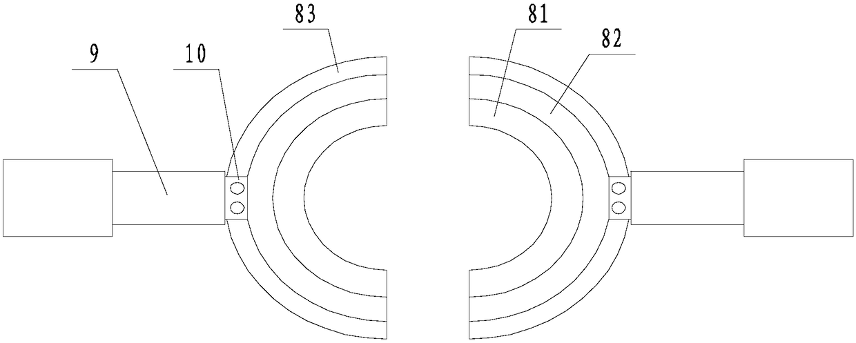
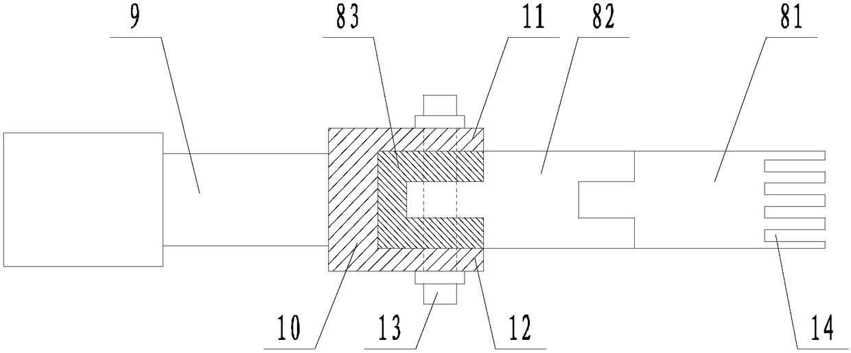
[0024] Such as Figure 1 to Figure 3The structure of a turntable with a built-in mud scraper is shown. On the basis of Embodiment 1, the control switch of the linear drive device 9 is located inside the driller's cabin. The mud scraper 8 is divided into a rubber layer 81, a ceramic layer 82, and a metal layer 83 from the inside to the outside. The inner wall of the ceramic layer 82 is provided with a groove, and the outer wall of the ceramic layer 82 is provided with a flange; The rubber layer 81 is extruded into the groove and glued to the groove wall of the groove; the flange is inserted into the metal layer 83; the driving end of the linear drive device 9 is fixedly connected to the mounting body 10. The installation body 10 includes an upper flange 11 and a lower flange 12 respectively located on the upper and lower sides of the metal layer 83, and also includes a The bolts 13; the inner wall of the rubber layer 81 is provided with several parallel cutouts 14. The rotary...


PUM


Abstract

The invention discloses a turntable structure with a built-in scraper. The turntable structure comprises a base body, a wellhead passage penetrating the base body, an annular rotating member rotatingaround the wellhead passage, and a centering complementing unit matching the annular rotating member. The annular rotating member is connected to an annular turntable; one loop of rack is fixed at theouter edge of the annular turntable in the circumferential direction. A gear and a rotary driving device are arranged in the base body; the gear is meshed with the rack; and the rotary driving devicedrives the gear to rotate. Two scraping pieces distributed symmetrically along the axis of the wellhead passage are arranged below the annular turntable; the scraping pieces are in a semi-annular shape; concave surfaces of the scraping pieces face the axis of the wellhead passage; each scraping piece is driven by one linear driving device to move; and the driving directions of the two linear driving devices are in a collinear state. Therefore, a problem that two drilling workers are need for completing scraping of the circumference of the surface of the drill rod during the drilling startingprocess in the prior art is solved; and thus the manpower consumption is reduced and the automatic scraping is realized.

Description

technical field [0001] The invention relates to the field of drilling rig turntables, in particular to a turntable structure with a built-in mud scraper. Background technique [0002] Oil drilling rigs are heavy mining machinery, which is a joint working unit composed of various machinery and equipment with multiple functions. In order to meet the drilling and completion process requirements, the entire drilling rig must have the following eight major system equipment: rotating equipment, circulation system equipment, hoisting system equipment, power drive system equipment, transmission system equipment, control system and monitoring instruments, drilling rig base, auxiliary equipment. Among them, the rotary equipment refers to the equipment used to rotate the drilling tool in the well and drive the drill bit to break the rock, including two types of rotary table drilling devices and top drive drilling devices. The turntable is the working machine of the rotary system and o...

Claims


Application Information

Patent Timeline
Patent Type & Authority Applications(China)
IPC IPC(8): E21B3/04E21B37/02
CPCE21B3/04E21B37/02
Inventor 黄玲曾道贵陈康
Owner 四川川油工程技术勘察设计有限公司
Why Eureka
Try Eureka