
Ventilating duct construction method

A technology for ventilation ducts and construction methods, which is applied in the direction of pipe cutting devices, manufacturing tools, metal processing equipment, etc., and can solve problems such as low work efficiency, potential safety hazards in ventilation duct cutting, and opening deflection

Inactive Publication Date: 2019-01-08
俞耀
View PDF0 Cites 2 Cited by
  • Summary
  • Abstract
  • Description
  • Claims
  • Application Information

AI Technical Summary

Problems solved by technology

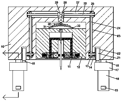
[0002] Ventilation pipes are metal or composite pipes used in ventilation and air-conditioning engineering of industrial and civil buildings. They are a kind of municipal infrastructure for air circulation and reducing the concentration of harmful gases. The shapes of ventilation pipes are various, and rectangular ventilation pipes are one of the commonly used ventilation pipes. , when constructing rectangular ventilation ducts, it needs to be cut. The common equipment for cutting rectangular ventilation ducts is a cutting machine. At present, manual cutting is usually used. It is easy to cause safety hazards when cutting, so it needs to be improved

Method used


Image

  • Ventilating duct construction method
  • Ventilating duct construction method
  • Ventilating duct construction method

Examples


Embodiment Construction

[0012] Combine below Figure 1-3 The present invention is described in detail, and for convenience of description, the orientations mentioned below are now stipulated as follows: figure 1 The up, down, left, right, front and back directions of the projection relationship itself are the same.

[0013] refer to Figure 1-3 , according to an embodiment of the present invention, a ventilation duct construction method includes a construction frame body 10 and a clamping assembly installed on the lower side of the construction frame body 10, and the bottom end surface of the construction frame body 10 is provided with an accommodating cavity 11 , the cutting body 12 is slidingly fitted in the accommodation chamber 11, and the top end surface of the cutting body 12 is symmetrically fixed with protrusions 33 on the left and right sides. The center is fixed with a piston rod 32, and the top of the piston rod 32 is dynamically equipped with a pneumatic cylinder 28. The pneumatic cylin...


PUM


Abstract

The invention discloses a ventilating duct construction method. According to the method, a construction frame body and a clamping and fixing assembly installed on the lower side of the construction frame body are involved, wherein a containing cavity is formed in the end surface of the bottom of the construction frame body, a cutting machine body is installed in the containing cavity in a slidingfit mode, convex blocks are bilaterally symmetrically and fixedly arranged on the end surface of the top of the cutting machine body, a buffering elastic piece is installed on the convex blocks, a piston rod is fixedly arranged in the right center of the top end of the buffering elastic piece, the top end of the piston rod is in power fit connection with an air pressure cylinder, the air pressurecylinder is fixedly arranged in the top wall of the containing cavity, concave cavities are bilaterally symmetrically formed in the positions, on the left side and the right side of the containing cavity, in the bottom end surface of the construction frame body, vertical transmission cavities are arranged in the positions, on the inner sides of the containing cavity, in the construction frame bodyin an up-and-down extension mode, the tail ends of the tops of the vertical transmission cavities communicate with transverse transmission cavities extending leftwards and rightwards, and a driving motor is fixedly arranged between the transverse transmission cavities on the left side and the right side.

Description

technical field [0001] The invention relates to the technical field of ventilation engineering, in particular to a construction method for ventilation pipes. Background technique [0002] Ventilation pipes are metal or composite pipes used in ventilation and air-conditioning engineering of industrial and civil buildings. They are a kind of municipal infrastructure for air circulation and reducing the concentration of harmful gases. The shapes of ventilation pipes are various, and rectangular ventilation pipes are one of the commonly used ventilation pipes. , when constructing rectangular ventilation ducts, it needs to be cut. The common equipment for cutting rectangular ventilation ducts is a cutting machine. At present, manual cutting is usually used. It is easy to cause safety hazards when cutting, so it needs to be improved. Contents of the invention [0003] The object of the present invention is to provide a ventilation duct construction method for overcoming the abo...

Claims


Application Information

Patent Timeline
Patent Type & Authority Applications(China)
IPC IPC(8): B23D21/00B23D33/00B23D33/02
CPCB23D33/02B23D21/00B23D33/00
Inventor 俞耀
Owner 俞耀
Learn More