
A Dead Zone Compensation Method Based on Discontinuous Pulse Width Modulation

A technology of pulse width modulation and dead zone compensation, which is applied in the direction of converting irreversible DC power input into AC power output, control system, control generator, etc. It can solve the problem of inverter output voltage amplitude reduction and low harmonic increase, motor electromagnetic torque pulsation increase, etc., to achieve the effect of reducing switching loss, improving conversion efficiency, and increasing fundamental wave amplitude

Active Publication Date: 2019-12-20
SOUTHWEST UNIVERSITY FOR NATIONALITIES
View PDF5 Cites 0 Cited by
  • Summary
  • Abstract
  • Description
  • Claims
  • Application Information

AI Technical Summary

Problems solved by technology

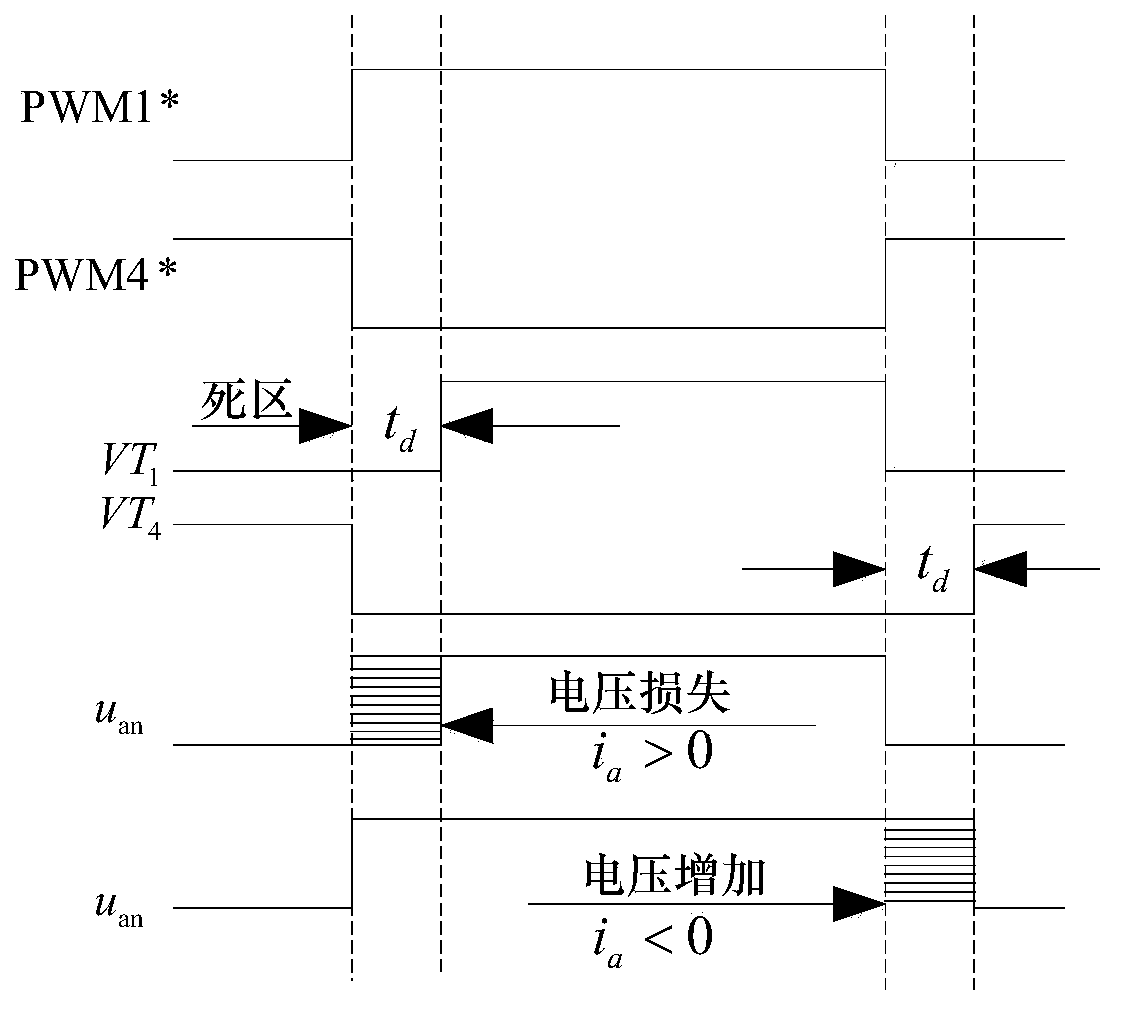
The dead time will cause the inverter output voltage amplitude to decrease, the low-order harmonics to increase, reduce the waveform quality of the stator current of the induction motor, increase the electromagnetic torque ripple of the motor, and the shape of the flux linkage is not regular enough
Therefore, it is necessary to compensate the voltage error caused by the dead zone. The most common method is to perform online or offline compensation for the duty ratio of each phase bridge arm. However, it is not applicable to the DPWM modulation strategy, because any switching cycle has a phase bridge arm The switching tube does not operate, that is, the duty cycle is 0, and the duty cycle of the phase cannot be modified. Therefore, a new compensation method needs to be adopted for the dead zone effect of the DPWM modulation strategy

Method used


Image

  • A Dead Zone Compensation Method Based on Discontinuous Pulse Width Modulation
  • A Dead Zone Compensation Method Based on Discontinuous Pulse Width Modulation
  • A Dead Zone Compensation Method Based on Discontinuous Pulse Width Modulation

Examples


Embodiment 1

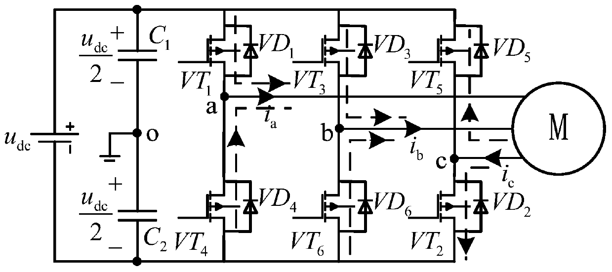
[0052] Embodiment 1: A dead zone compensation method based on discontinuous pulse width modulation, said method is used in a three-phase voltage source inverter system for driving an induction motor, comprising the following steps:

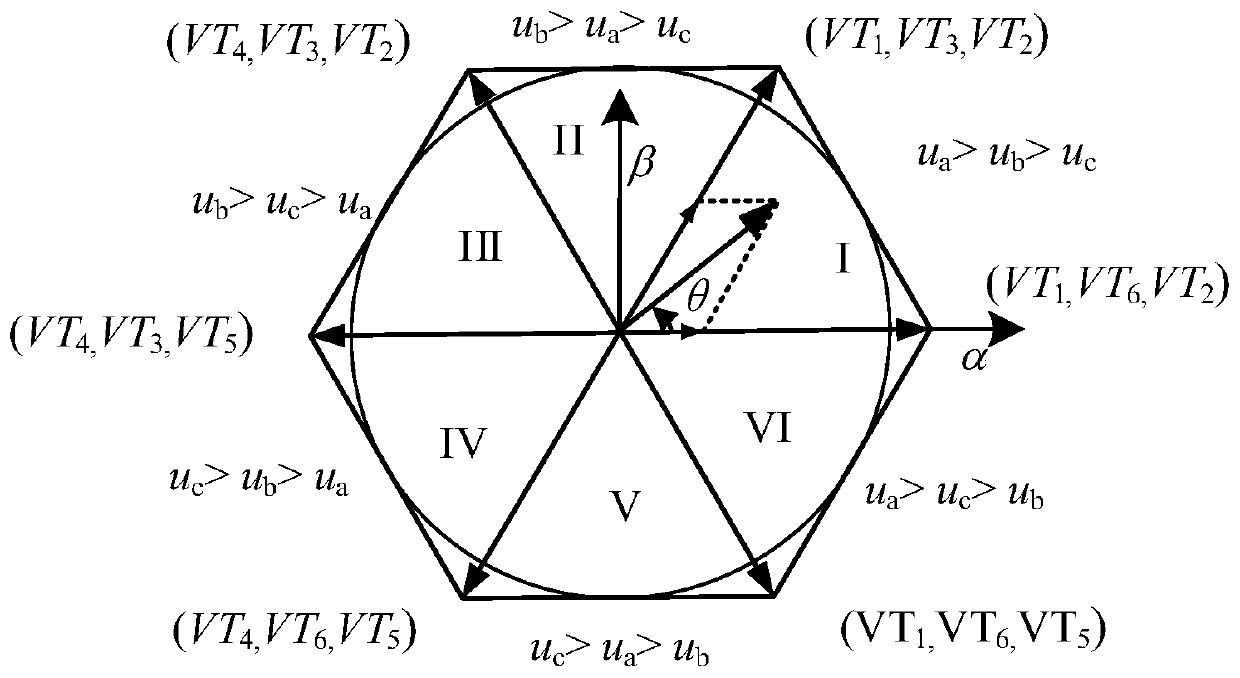
[0053] The first step is to consider the device turn-on delay time t on , turn-off delay time t off , dead zone setting time t d , the switching period is T s , the conduction voltage drop u of the switching device vt , the tube voltage drop u of the antiparallel diode vd , according to the sector where the target voltage vector is located, and the three-phase stator current i a i b i c According to their respective polarities, the voltage errors of a, b, and c three-phase relative to the DC bus of the lower bridge arm generated by the dead zone are shown in Table 1:

[0054] Table I

[0055]

[0056] which is:

[0057] ① When the voltage vector is in sector I and sector II:

[0058] if i a >0, then Δu an =Δu 3 ; if i a an =Δu 4 ...

Embodiment 2

[0099] Embodiment 2, the dead zone compensation method based on discontinuous pulse width modulation is implemented on the experimental platform of the voltage source inverter (voltage source inverter, VSI) induction motor drive system. The prototype includes a DC 48V voltage source composed of a battery pack, control and drive System, induction motor and counter motor, speed torque measurement device. First implement the dead zone compensation method under the condition of no-load 1000r / min, then add the voltage feedforward compensation program to the DPWM modulation program, set the switching frequency to 10kHz, and set the dead zone time to 2 microseconds; see Figure 5 , the specific dead zone compensation method is:

[0100] 1. First, according to u dc , θ Calculate the duty ratio of the upper bridge arm of each phase.

[0101] 2. Use the current sensor to detect the current of each phase of the three-phase stator, filter the phase current through a low-pass filter, a...


PUM


Abstract

The invention discloses a novel dead zone compensation method based on discontinuous pulse width modulation, which is characterized in that it includes the following steps: according to the sector where the target voltage vector is located and the respective polarities of the three-phase stator currents, the dead zone generated by the dead zone is obtained The voltage error of the three phases a, b, and c relative to the DC bus of the lower bridge arm; according to the voltage error, the respective phase voltage errors of the three phases a, b, and c caused by the dead zone and the tube voltage drop are obtained; the phase voltage error is carried out The equal-amplitude transformation of the three-phase stationary to the two-phase stationary coordinate system obtains the voltage error of the phase voltage in the two-phase stationary coordinate system; combined with the real-time rotor flux position angle, the phase voltage error in the two-phase rotating coordinate system is calculated; Perform voltage feed-forward compensation on the phase voltage; finally, according to the command voltage in the two-phase rotating coordinate system obtained after the voltage feed-forward compensation, as well as the rotor flux angle and the DC bus voltage, execute the DPWM modulation strategy; the invention can be widely used in AC Drive system and photovoltaic grid-connected system.

Description

technical field [0001] The invention relates to a discontinuous pulse width modulation method, in particular to a dead zone compensation method based on discontinuous pulse width modulation. Background technique [0002] Compared with the traditional space vector modulation strategy, discontinuous pulse modulation strategy (discontinuous pulse modulation strategy, DWPM) can effectively reduce the number of switching, thereby reducing switching loss and improving the voltage source inverter system (voltage source inverter, VSI ) conversion efficiency. Since there is a delay when the switching device is turned off, in order to prevent the DC power supply from being burned due to the direct current of the upper and lower bridge arms of the inverter, it is necessary to add a turn-on delay to the driving signal of a switching device. The time during which they are both in the off state is called the dead time. The dead time will cause the inverter output voltage amplitude to de...

Claims


Application Information

Patent Timeline
Patent Type & Authority Patents(China)
IPC IPC(8): H02M1/38H02M7/48H02P21/00
CPCH02M1/38H02M7/48H02P21/00H02M1/0012H02M1/385Y02E10/56
Inventor 宋鹏云
Owner SOUTHWEST UNIVERSITY FOR NATIONALITIES
Learn More