
Anaerobic reaction tank

An anaerobic reaction tank and tank body technology, applied in anaerobic digestion treatment, biological water/sewage treatment, water/sludge/sewage treatment, etc. The volume of the pre-acidification pool and other issues can be improved to improve the reaction effect of wastewater, to operate quickly, and to reduce the clogging rate.

Pending Publication Date: 2019-01-04
广西绿晨环境工程有限公司
View PDF0 Cites 2 Cited by
  • Summary
  • Abstract
  • Description
  • Claims
  • Application Information

AI Technical Summary

Problems solved by technology

The return of the anaerobic effluent from the anaerobic reactor to the pre-acidification tank will occupy the volume of the pre-acidification tank, which reduces the residence time of the wastewater and is not conducive to anaerobic digestion; on the other hand, after the return water enters the pre-acidification tank, it needs to be raised again To the anaerobic reactor, resulting in a great waste of energy and high operating costs
At the same time, the return flow control is inaccurate and inflexible, which consumes a lot of energy and costs high

Method used


Image

  • Anaerobic reaction tank
  • Anaerobic reaction tank

Examples


specific Embodiment 1

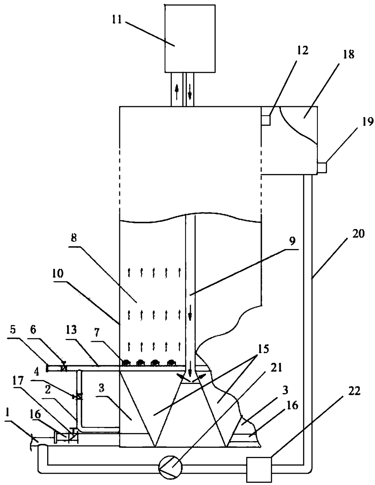
[0030] Such as figure 1 As shown, a kind of anaerobic reaction tank, comprises tank body 10, and the lower part of described tank body 10 is distributed with the dividing plate that longitudinal section is nearly " W " shape, and this dividing plate divides the lower part of described tank body 10 into a circle The water inlet distribution chamber 3 and a circle of sand collection chamber 15; the water inlet distribution chamber 3 is connected with the main water inlet pipe 1; the water inlet distribution chamber 3 is also connected with ten water inlet distribution pipes 2, of course, the water inlet The number of pipes 2 is not limited thereto, and can be selectively distributed according to needs. The water inlet distribution pipe 2 is evenly distributed around the outer circumference of the water inlet distribution chamber 3; the water inlet distribution pipe 2 is also combined with positive flushing Valve 4; ten water distribution branch pipes 13 are also distributed on t...

specific Embodiment 2

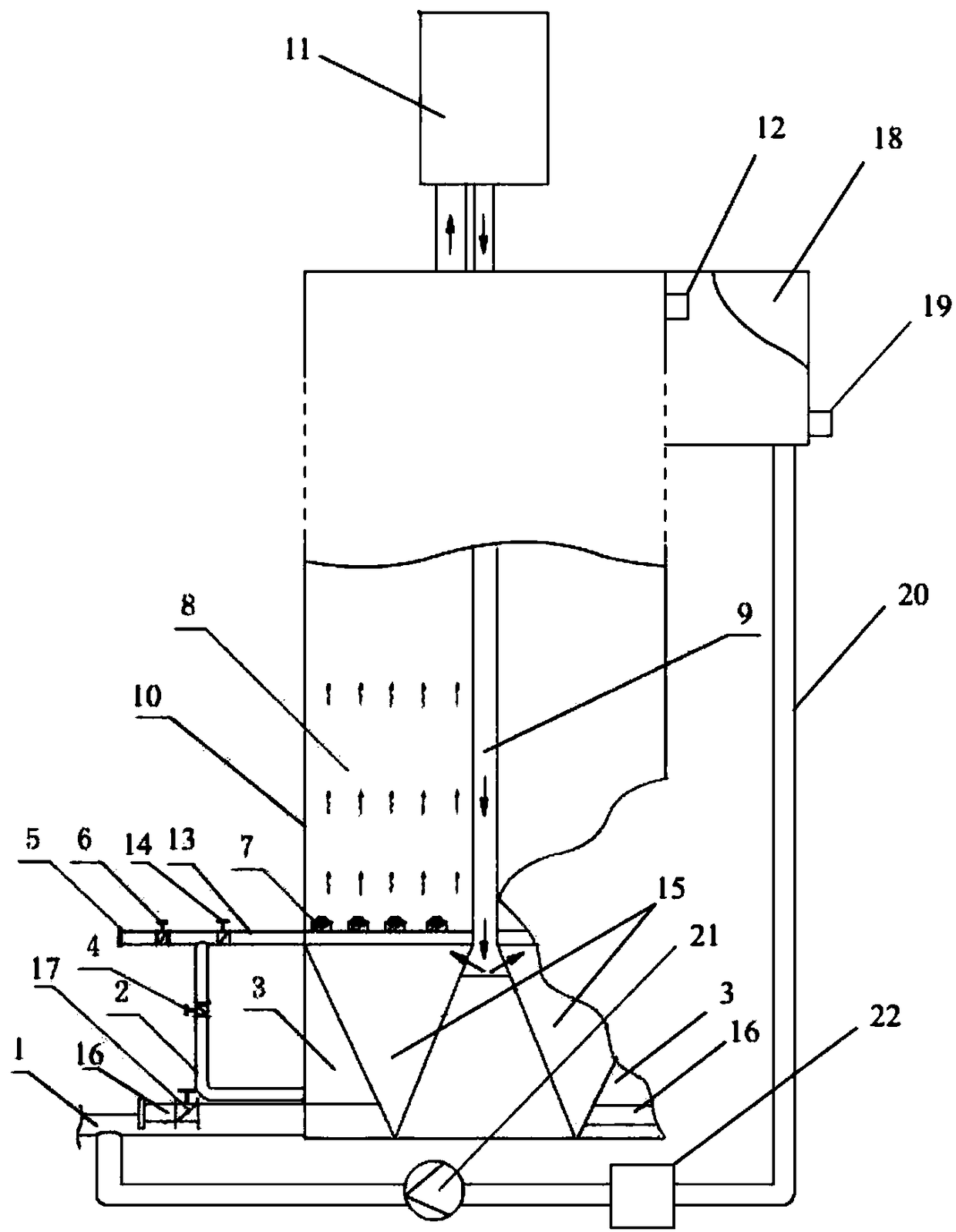
[0032] The difference between this embodiment and the specific embodiment only lies in: figure 2 As shown, the water distribution branch pipe 13 is also provided with a secondary valve 14, and the secondary valve 14 is distributed on the side of the tank where the water inlet distribution pipe 2 and the water distribution branch pipe 13 are connected. The secondary valve 14 is mainly used for finding and dredging blocked pipelines, and its function is as described in the beneficial effects of the present invention compared with the prior art.


PUM


Abstract

The invention discloses an anaerobic reaction tank. The anaerobic reaction tank is characterized in that a partition plate with a nearly 'W'-shaped longitudinal section is distributed on the lower portion of a tank, and the lower portion of the tank is divided into a circle of water inlet distribution cavities and a circle of sediment collecting cavities by the partition plate; a main water inletpipe is communicated with the water inlet distribution cavities; a plurality of water distribution branch pipes are further distributed on the tank; a plurality of water distributors are further distributed on the portions, which are distributed in the tank, of the water distribution branch pipes; the water distributors are distributed above the sediment collecting cavities; the water distributionbranch pipes are communicated with the water inlet distribution cavities; a plurality of sediment discharge pipes are communicated with the lower portions of the sediment collecting cavities, and theouter ends of the sediment discharge pipes extend out of the tank; valves are further distributed on the sediment discharge pipes, and a potential energy circulator is further arranged on the upper portion of the tank. The anaerobic reaction tank has the advantages of uniform water distribution, good reaction effect, difficulty in blockage, easiness in checking blockage, efficient blockage removal, good sediment settling and collecting effects, simplicity and convenient in sediment discharge and stable integral operation.

Description

technical field [0001] The invention relates to the technical field of sewage treatment equipment, in particular to an anaerobic reaction tank. Background technique [0002] With the rapid development of modern industry, especially organic chemical industry, petrochemical industry, dyestuff, medicine, pesticide and other chemical industries, various refractory organic wastewaters are increasing. These wastewaters generally have high pollutant concentration, high suspended solid content, and high toxicity. , The characteristics of poor biodegradability, serious pollution of water environment, endangering human health. [0003] High-concentration organic wastewater is a major industrial pollution source that is difficult to treat, with high COD concentration. At present, the domestic high-concentration organic wastewater treatment will apply anaerobic treatment technology, but in the water distribution of the anaerobic reactor, the traditional perforated water distribution, o...

Claims


Application Information

Patent Timeline
Patent Type & Authority Applications(China)
IPC IPC(8): C02F3/28
CPCC02F3/28C02F3/2866C02F3/2873
Inventor 聂威李彪乐简剑
Owner 广西绿晨环境工程有限公司
Learn More