
Silicon rod squaring equipment, silicon rod squaring method and flaw piece unloading device

A technology of unloading device and carrying device, which is applied in the direction of stone processing equipment, fine working devices, working accessories, etc. It can solve the problems of low unloading efficiency of edge skin and damage of silicon rods, etc., so as to improve the overall operating efficiency, improve efficiency, and improve The effect of work efficiency

Pending Publication Date: 2019-01-04
TDG NISSIN PRECISION MACHINERY CO LTD
View PDF11 Cites 18 Cited by
  • Summary
  • Abstract
  • Description
  • Claims
  • Application Information

AI Technical Summary

Problems solved by technology

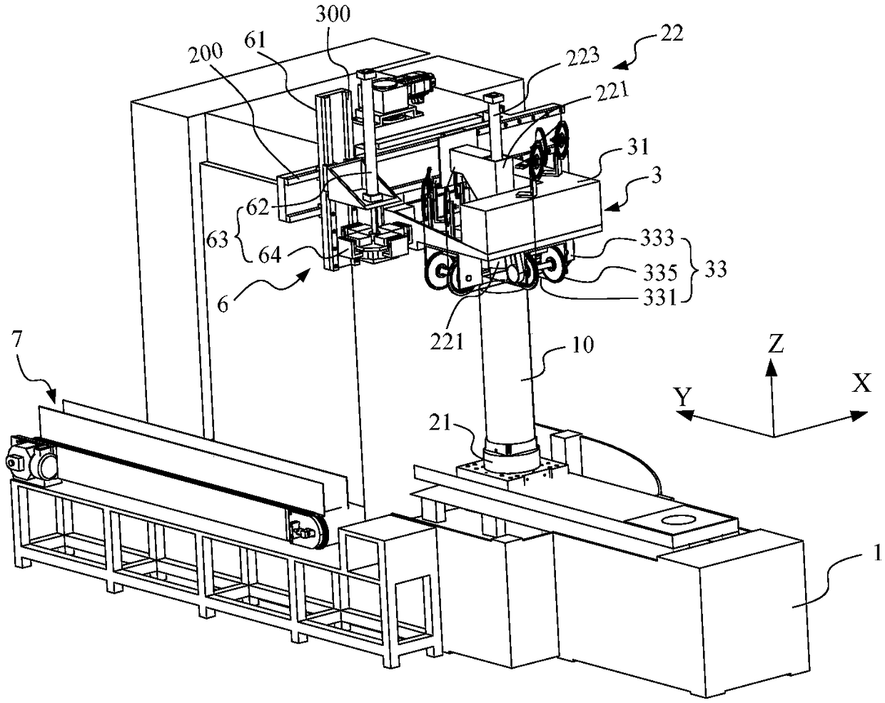
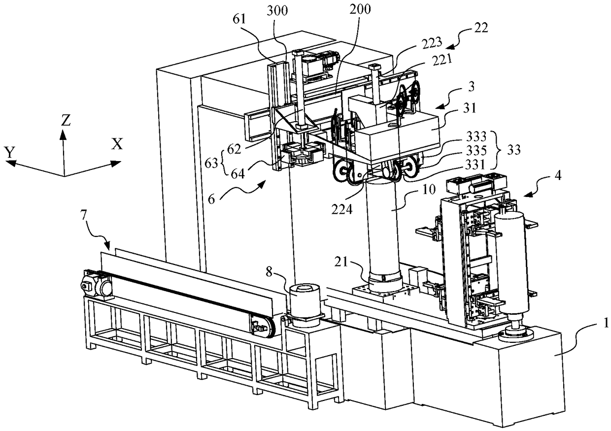
[0006] In view of the lack of the above-mentioned related technologies, the purpose of this application is to disclose a silicon rod squaring equipment, a silicon rod squaring method and a side skin unloading device, which are used to solve the problem of side skin unloading in the silicon rod squaring cutting operation in the related technology. Low efficiency and easy to cause damage to silicon rods

Method used


Image

  • Silicon rod squaring equipment, silicon rod squaring method and flaw piece unloading device
  • Silicon rod squaring equipment, silicon rod squaring method and flaw piece unloading device
  • Silicon rod squaring equipment, silicon rod squaring method and flaw piece unloading device

Examples


Embodiment Construction

[0034] The embodiments of the present application are described below by specific specific examples, and those skilled in the art can easily understand other advantages and effects of the present application from the contents disclosed in this specification.

[0035] In the following description, reference is made to the accompanying drawings, which describe several embodiments of the present application. It is to be understood that other embodiments may be utilized and mechanical, structural, electrical, as well as operational changes may be made without departing from the spirit and scope of the present application. The following detailed description should not be considered limiting, and the scope of embodiments of the present application is limited only by the claims of the issued patent. The terminology used herein is for the purpose of describing particular embodiments only and is not intended to limit the application. Spatially related terms, such as "upper," "lower," ...


PUM


Abstract

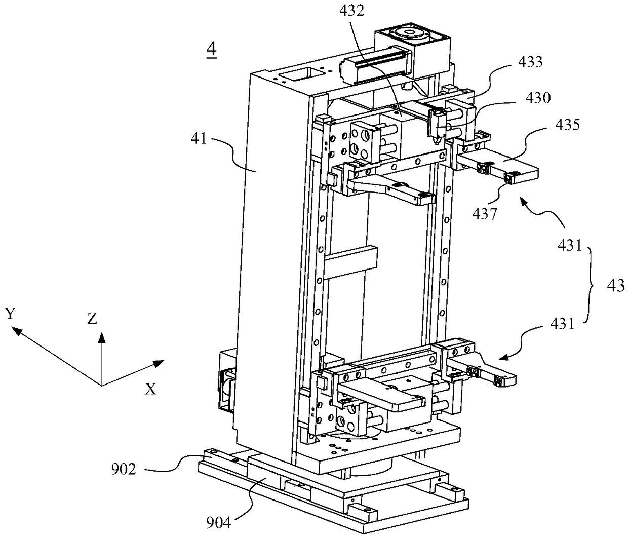
The invention discloses silicon rod squaring equipment, a silicon rod squaring method and a flaw piece unloading device. The silicon rod squaring equipment comprises a silicon rod bearing device, a linear cutting device and the flaw piece unloading device. The linear cutting device comprises a linear cutting support and a linear cutting unit. A cutting line segment is arranged in the linear cutting unit, the cutting line segment in the linear cutting unit penetrates through a to-be-cut silicon rod by driving the linear cutting support to descend, and the cut silicon rod and a flaw piece are formed. The flaw piece unloading device comprises a flaw piece lifting mechanism and a line thumbing mechanism. The line thumbing mechanism thumbs the cutting line segment to expand outwards, so that interference between the cutting line segment and the cut silicon rod is avoided. According to the technical scheme, the flaw piece can be stably lifted under the condition that it is guaranteed that the cutting line segment does not interfere with the cut silicon rod, thus, the efficiency of squaring cutting work of the silicon rod can be improved, the squared flaw piece is lifted in an unobstructed manner and then unloaded, operation is convenient, and the overall working efficiency is improved.

Description

technical field [0001] The present application relates to the technical field of crystalline silicon processing, and in particular, to a silicon rod cutting device, a silicon rod cutting method and an edge skin unloading device. Background technique [0002] In the manufacture of various semiconductor devices or photovoltaic devices, semiconductor workpieces containing hard and brittle materials such as silicon, sapphire, or ceramics are cut into specific-sized structures. Since the cutting of semiconductor workpieces is an important process that restricts subsequent finished products, the requirements for its operations are getting higher and higher. At present, multi-wire cutting technology is widely used in the cutting and production of semiconductor workpieces in the industry due to its high production efficiency, low operating cost, and high operating accuracy. [0003] The existing production process of silicon wafers, taking monocrystalline silicon products as an exa...

Claims


Application Information

Patent Timeline
IPC IPC(8): B28D5/04B28D7/00B28D7/04
CPCB28D5/0058B28D5/0082B28D5/045Y02P70/50
Inventor 潘雪明李鑫
Owner TDG NISSIN PRECISION MACHINERY CO LTD
Learn More