
Glass multi-sided edging machine

A kind of edging machine and multi-edge technology, which is applied to the parts of grinding machine tools, machine tools and grinding machines suitable for grinding the edge of workpieces, etc. Quality and other issues, to achieve the effect of convenient operation, simple structure, convenient and fast handling and movement

Inactive Publication Date: 2019-01-04
黄清平
View PDF0 Cites 2 Cited by
  • Summary
  • Abstract
  • Description
  • Claims
  • Application Information

AI Technical Summary

Problems solved by technology

[0004] In the process of glass processing, in order to be suitable for various specific use environments, it needs to be cut into different shapes and forms of glass according to the needs. However, during the cutting process, the edge of the glass will produce capillary and rough conditions. In order to meet the needs, it needs to be edging The edger grinds the cut glass; the edger is set up for this purpose, but the existing edger is in the edger process, because the glass is edger in the motion process, because the conveyor belt The unevenness and the vibration generated by edging often cause the glass to jump during the edging process, which will affect the edging quality of the glass, and cause the scrapping of the glass and the damage of the grinding wheel if it is serious, and most of the glass is rectangular. It is necessary to perform chamfering on all four sides. When the existing machines can only chamfer and grind one side, they cannot complete chamfering and edging on multiple sides at the same time. Such processing is time-consuming and laborious.

Method used


Image

  • Glass multi-sided edging machine
  • Glass multi-sided edging machine

Examples


Embodiment Construction

[0016] Any feature disclosed in this specification, unless specifically stated, can be replaced by other alternative features that are equivalent or have similar purposes. That is, unless expressly stated otherwise, each feature is one example only of a series of equivalent or similar features.

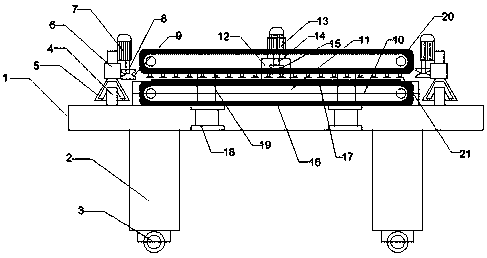
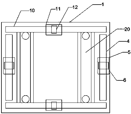
[0017] Such as figure 1 and figure 2 A glass polygonal edging machine shown includes a workbench 1, a support frame 2 is arranged under the workbench 1, a universal wheel 3 is arranged under the support frame 2, and first Slide rail 4, the first slide block 5 is set on the first slide rail 4, the first lifting device 6 is set on the first slide block 5, the first motor 7 is set on the first lifting device 6, on the first The first output shaft 8 is set under the motor 7, the first multi-faceted edging block 9 is set under the first output shaft 8, and the second slide rail 10 is respectively set on the front and rear sides of the workbench 1, and the second slide rail 10 The secon...


PUM


Abstract

The invention discloses a glass multi-sided edging machine. The glass multi-sided edging machine comprises a workbench; a support frame is arranged under the workbench; a first sliding block is arranged on a first sliding rail; a first lifting device is arranged on the first sliding block; a first motor is arranged on the first lifting device; a first output shaft is arranged under the first motor; a first multi-sided edging block is arranged under the first output shaft; a second sliding block is arranged on a second sliding rail; a second lifting device is arranged on the second sliding block; a second motor is arranged on the second lifting device; a second output shaft is arranged under the second motor; a second multi-sided edging block is arranged under the second output shaft; a first conveyor belt is arranged on the workbench; and air cylinders are arranged under the left side and the right side of the workbench. The glass multi-sided edging machine is simple in structure and convenient to use, the motors are arranged on the four sides, a glass pane can be edged at the same time, the work efficiency is improved, and three sides of the glass pane are simultaneously edged through multi-sided grinding heads during edging.

Description

technical field [0001] The invention relates to the technical field of glass processing equipment, in particular to a glass polygonal edging machine. Background technique [0002] Glass edging machine is one of the earliest and most widely used mechanical equipment in glass deep processing equipment. The main function is to smooth the glass and make some special shapes. The correct and reasonable use of the edging machine can not only ensure the normal production, but also prolong the life of the machine. It is divided into single-arm special-shaped edging machine, linear edging machine, and profiling edging machine. [0003] Glass edging machine is mainly suitable for the processing of furniture glass, architectural glass and craft glass. It is one of the earliest and most widely used cold processing equipment in glass machinery deep processing equipment. It is mainly used for grinding and polishing the bottom edge and chamfer of ordinary flat glass. Generally, there ar...

Claims


Application Information

Patent Timeline
Patent Type & Authority Applications(China)
IPC IPC(8): B24B9/10B24B27/00B24B41/00B24B41/06
CPCB24B9/10B24B27/0076B24B41/005B24B41/06
Inventor 黄清平
Owner 黄清平
Learn More