
A Miniature Free Piston Generator with Compound Combustion Chamber Structure

A combustion chamber and generator technology, applied in the field of micro-power systems, can solve the problems that the integration and modularization of micro-free piston generators cannot be realized, the utilization of waste heat of exhaust gas is not considered, and the space occupancy rate is high. The ignition timing is advanced and the space occupation rate is small.

Active Publication Date: 2020-11-03
JIANGSU UNIV
View PDF7 Cites 0 Cited by
  • Summary
  • Abstract
  • Description
  • Claims
  • Application Information

AI Technical Summary

Problems solved by technology

[0003] Among the various miniature free-piston generator technologies disclosed at present, for example, the patent with the publication number CN107740727A preheats the intake air of the generator to increase the initial temperature of the mixture gas, thereby improving the efficiency of the generator, but it does not consider the use of exhaust gas waste heat. One form - thermoelectric power generation; at the same time, most of the current miniature free-piston generators adopt an opposed arrangement, which has a high space occupation rate and a complicated structure, which makes it impossible to realize the integration and modularization of the miniature free-piston generator

Method used


Image

  • A Miniature Free Piston Generator with Compound Combustion Chamber Structure
  • A Miniature Free Piston Generator with Compound Combustion Chamber Structure
  • A Miniature Free Piston Generator with Compound Combustion Chamber Structure

Examples


Embodiment Construction

[0036] The present invention will be further described below in conjunction with the drawings and specific embodiments, but the protection scope of the present invention is not limited thereto.

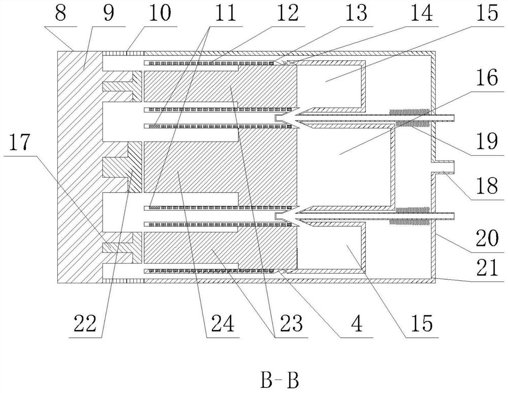
[0037] Such as Figure 1-Figure 3 As shown, the miniature free piston generator with a compound combustion chamber structure according to the present invention includes a first miniature free piston power device 7, a second miniature free piston power device 5, and a body 1. The body 1 is provided with a first A miniature free piston power unit 7 and a second miniature free piston power unit 5. The first miniature free piston power unit 7 is provided with a first combustion chamber 16, and the first combustion chamber 16 is provided with an air inlet and a second The air outlet 6 of a miniature free piston power unit, the second miniature free piston power unit 5 is provided with a second combustion chamber 15, and the second combustion chamber 15 is provided with an air inlet and a seco...


PUM


Abstract

The invention provides a miniature free piston generator with a compound combustion chamber structure. The miniature free piston generator comprises a hydraulic cylinder and a temperature difference power generation device; a first miniature free piston power device is located on an axis of a machine body, and a plurality of second miniature free piston power devices are uniformly distributed in the circumferential direction of the axis of the machine body; a plurality of air inlets and a generator exhaust port are formed in the machine body, and the exhaust port of the generator communicateswith an inner cavity of the machine body; the hydraulic cylinder comprises a first piston rod, a second piston rod and a hydraulic cavity, wherein the hydraulic cavity is connected with the machine body, the first piston rod and the plurality of second piston rods are arranged in the hydraulic cavity, and a piston body of the first miniature free piston power device is in linkage with the first piston rod; piston bodies of the second miniature free piston power devices are in linkage with a second piston rod; and the temperature difference power generation device is arranged in the machine body. According to the generator, mechanical energy of piston movement can be directly converted into electric energy so as to obtain a relatively high energy conversion rate; and preheating is carried out on the mixed incoming air by utilizing high-temperature waste gas.

Description

Technical field [0001] The invention relates to a micro-power system related to the field of internal combustion engines and power generation, in particular to a micro free piston generator with a compound combustion chamber structure. Background technique [0002] The vigorous development of micro power systems will produce profound changes in various industries, such as biomedicine, drone detection, and portable power supplies. The micro power plant has the characteristics of small structure and large output power, and has broad application prospects. The structure of the miniature free piston power unit does not have the crank connecting rod and valve of the traditional internal combustion engine, and the compression ratio is variable. By combining with the HCCI (Homogeneous charge compression ignition) combustion method, it can overcome the quenching and quenching caused by the micro-scale combustion. Problems such as unstable combustion and narrow fire limits. Most of the ...

Claims


Application Information

Patent Timeline
Patent Type & Authority Patents(China)
IPC IPC(8): F02B71/04F02B71/02F02B73/00F02M31/087F01N5/02F02B23/04F02F3/12F02F1/22F02B37/00F02B35/00H02K7/18H02N11/00
CPCF01N5/025F02B23/04F02B35/00F02B37/00F02B71/02F02B71/04F02B73/00F02F1/22F02F3/12F02F2003/0007F02M31/087H02K7/1884H02N11/002Y02T10/12
Inventor 赵岩王谦吴凡柏金
Owner JIANGSU UNIV
Learn More