An Ultra-Low Power Biased RF Switch

A radio frequency switch, ultra-low power consumption technology, applied in the direction of electronic switches, energy consumption reduction, advanced technology, etc., can solve the problems of rising chip cost and occupying a large chip area, so as to reduce area and cost, save capacitor area, and maintain performance effect

Active Publication Date: 2022-05-24
安徽矽磊电子科技有限公司
View PDF5 Cites 0 Cited by
  • Summary
  • Abstract
  • Description
  • Claims
  • Application Information

AI Technical Summary

Problems solved by technology

[0005] However, the SOI radio frequency switch has the following problems: because a high-power input signal often requires a switch drive circuit, wherein the switch drive circuit includes a negative voltage generating circuit, which is used to generate a negative voltage to provide bias for the gate and body in the closed branch. set, such as figure 2 shown
[0007] But there is a problem with the above structure: combining Figure 4 The complete SP4T antenna switch shown shows that the number of capacitors will increase with the increase of the number of throws. Each branch needs four parallel capacitors. Two capacitors are on both sides of the series stacked transistor unit. The other two capacitors are respectively On both sides of the parallel stacked transistor unit, these capacitances are much larger than the parasitic capacitance of the transistor itself to reduce the influence of the nonlinearity of the parasitic capacitance. Therefore, generally these capacitances are implemented with a MIM or MOM structure, which will occupy a large amount of chip area and cause chip Costs have risen sharply
[0008] It can be seen from the above that there is still a need for further improvement in the design of the existing SOI RF switch in terms of power consumption and volume

Method used


Image

  • An Ultra-Low Power Biased RF Switch
  • An Ultra-Low Power Biased RF Switch
  • An Ultra-Low Power Biased RF Switch

Examples


Embodiment Construction

[0033] In order to make the objectives, technical solutions and advantages of the present invention clearer, the embodiments of the present invention will be described in detail below with reference to the accompanying drawings. It should be noted that, the embodiments in the present application and the features in the embodiments may be arbitrarily combined with each other if there is no conflict.

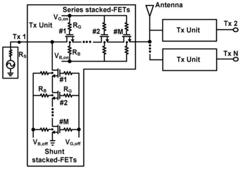
[0034] In order to further improve the power consumption, volume, and cost of the existing radio frequency switch, the embodiment of the present invention provides an improved ultra-low power consumption biased radio frequency switch. The specific circuit diagram is as follows Figure 5 shown. Wherein, the radio frequency switch unit is used to process the data to be transmitted (encoded and modulated) on the transmission path TX. But not limited, it can also be used to process the data to be received on the receiving path RX. In the transceiver path, the antenna Antenna is used...


PUM


Abstract

The present invention proposes a new radio frequency switch structure: each radio frequency switch includes a series branch and a parallel branch, the series branches through different radio frequency switches share an AC coupling capacitor, the parallel branch and the parallel branch in the same radio frequency switch The series branch shares an AC coupling capacitor, removes the blocking transistor and the AC coupling capacitor close to the ground in the parallel branch of the same radio frequency switch, does not need any negative voltage generating circuit, and can save more than 60% of the capacitor area compared with the traditional structure. The invention greatly reduces the area and cost of the chip while keeping the performance unchanged.

Description

technical field [0001] The invention relates to the field of radio frequency signal processing, in particular to an ultra-low power consumption biased radio frequency switch. Background technique [0002] High-quality RF switches are key components of multi-mode, multi-frequency, and multi-standard wireless RF transceivers, especially in time-division duplex wireless systems, where they play an irreplaceable role. The application of RF switches in the rapidly developing 3G / 4G multi-mode and multi-band terminals is becoming more and more extensive, and the complexity of RF terminals is increasing, especially for the application requirements of "five-mode and thirteen-band" proposed by China Mobile. The demand leads to the use of at least multiple RF switches in the RF terminal to switch between different frequency bands and modes at the data, voice, and diversity receiving ends respectively. As the complexity of the system increases, the usage of switches in the RF system wi...

Claims


Application Information

Patent Timeline
Patent Type & Authority Patents(China)
IPC IPC(8): H03K17/687
CPCH03K17/687H03K2217/0036Y02D30/70
Inventor 王晗
Owner 安徽矽磊电子科技有限公司
Why Eureka
Try Eureka