Multiplex output power supply

A multi-channel output and power supply technology, which is applied in the direction of output power conversion devices, electrical components, DC power input conversion to DC power output, etc., can solve problems such as high cost, unsatisfactory customer timing applications, and large space occupation, etc., to achieve Low cost, easy design, and space-saving effect

Pending Publication Date: 2018-12-21
MORNSUN GUANGZHOU SCI & TECH
View PDF0 Cites 0 Cited by
  • Summary
  • Abstract
  • Description
  • Claims
  • Application Information

AI Technical Summary

Problems solved by technology

[0002] In today's switching power supply production, many switching power supply products have achieved multi-channel output to meet the needs of customers with multiple devices, and at the same time greatly reduce costs. Switching power supply products have become the first choice for customers; at present, many devices require a sequence of startup or shutdown, for example, one device starts first, and other devices start after a period of delay to ensure the normal operation or storage of the device Data, etc.; the current industry solution is to use a sequential power supply socket or multiple switching power supply products and software compatible implementations, such as figure 1 , but this leads to high cost and large space occupation, which is not what manufacturers and customers want, nor is it the optimal solution; and the cost of using a single switching power supply with multiple outputs is optimal, and the main and auxiliary circuits are both Satisfy the isolation of safety regulations, but the output voltage of the main circuit and auxiliary circuit of the switching power supply product is established almost at the same time, which does not meet the customer's timing application

Method used


Image

  • Multiplex output power supply
  • Multiplex output power supply
  • Multiplex output power supply

Examples


no. 1 example

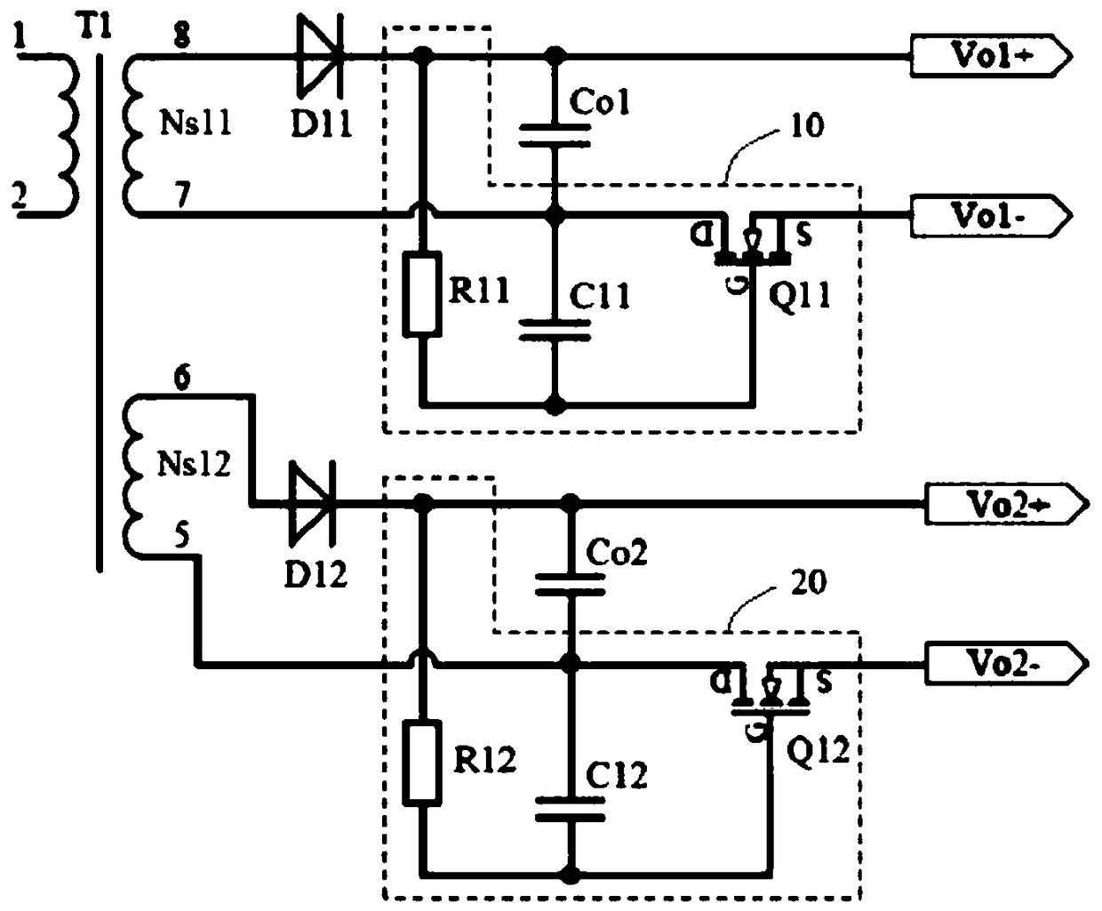
[0027] Such as image 3 As shown, it is a schematic diagram of the multi-output power supply of the first embodiment of the present invention. A multi-output power supply includes at least two secondary windings of transformers, and one secondary winding forms the main output circuit (hereinafter referred to as the main output circuit). circuit), other secondary windings form an auxiliary output circuit (hereinafter referred to as auxiliary circuit), and the timing control circuit 10 of the main output circuit and the timing control circuit 20 of the auxiliary output circuit can be set as required to realize the multi-channel equipment in the application system. Time-sequential power supply is required; there may also be only the timing control circuit 10 of the main output circuit or the timing control circuit 20 of the auxiliary output circuit. The timing control circuit has the same structure in the main and auxiliary output circuits. The timing control circuit 10 of the ma...

no. 2 example

[0043] Such as Figure 4 As shown, it is a schematic diagram of the multi-output power supply of the second embodiment of the present invention. A multi-output power supply is different from the first embodiment in that a stable capacitor is connected in series between the positive electrode of the capacitor C1 and the driving pin of the MOS transistor Q1. Voltage tube Z1; that is, the voltage regulator tube Z1 is connected in series between the gate of the MOS transistor Q1 and the connection end of the resistor R1 and the capacitor C1, the anode of the voltage regulator tube Z1 is connected to the grid of the MOS tube Q1, and the cathode of the voltage regulator tube Z1 Connect one end of the resistor R1 and the other end of the capacitor C1 respectively.

[0044] Now take the timing control circuit of the main output circuit as an example to illustrate its connection relationship as follows: the timing control circuit includes MOS tube Q11, resistor R11, capacitor C11 and v...


PUM


Abstract

The invention provides a multi-output power supply comprising at least one sequential control circuit. Multiple sequential outputs can be achieved and the settling time of each output voltage can be set as needed. It is used to control the auxiliary circuit delay turn-on output of the switching power supply product, so as to solve the sequential start-up application requirements of multiple devices of the customer, reduce the cost and occupy small space. When this circuit can be used in the switching power supply with more than two outputs, the effect is the most obvious.

Description

technical field [0001] The invention relates to the field of switching power supplies, in particular, to a switching power supply with multiple outputs. Background technique [0002] In today's switching power supply production, many switching power supply products have achieved multi-channel output to meet the needs of customers with multiple devices, and at the same time greatly reduce costs. Switching power supply products have become the first choice for customers; at present, many devices require a sequence of startup or shutdown, for example, one device starts first, and other devices start after a period of delay to ensure the normal operation or storage of the device Data, etc.; the current industry solution is to use a sequential power supply socket or multiple switching power supply products and software compatible implementations, such as figure 1 , but this leads to high cost and large space occupation, which is not what manufacturers and customers want, nor is ...

Claims


Application Information

Patent Timeline
Patent Type & Authority Applications(China)
IPC IPC(8): H02M3/07
CPCH02M3/073H02M3/075
Inventor 卢六里宋建峰程志勇
Owner MORNSUN GUANGZHOU SCI & TECH
Why Eureka
Try Eureka