A new type of rail potential limiting device

A limiting device and rail potential technology, which is applied in the field of new rail potential limiting devices, can solve problems such as easy-to-burn devices, rail potential limiting device failures, and inability to reset, so as to reduce stray currents and ensure safety.

Pending Publication Date: 2018-12-21
CHENGDU ZHONGGONG ELECTRIC ENG
View PDF0 Cites 5 Cited by
  • Summary
  • Abstract
  • Description
  • Claims
  • Application Information

AI Technical Summary

Problems solved by technology

[0018] (5) Failure of the rail potential limiting device
[0021] 1. The existing rail potential limiting device is prone to long-term locking after frequent actions, and cannot be reset in time
Manual reset is required after manual confirm

Method used


Image

  • A new type of rail potential limiting device
  • A new type of rail potential limiting device
  • A new type of rail potential limiting device

Examples


Embodiment Construction

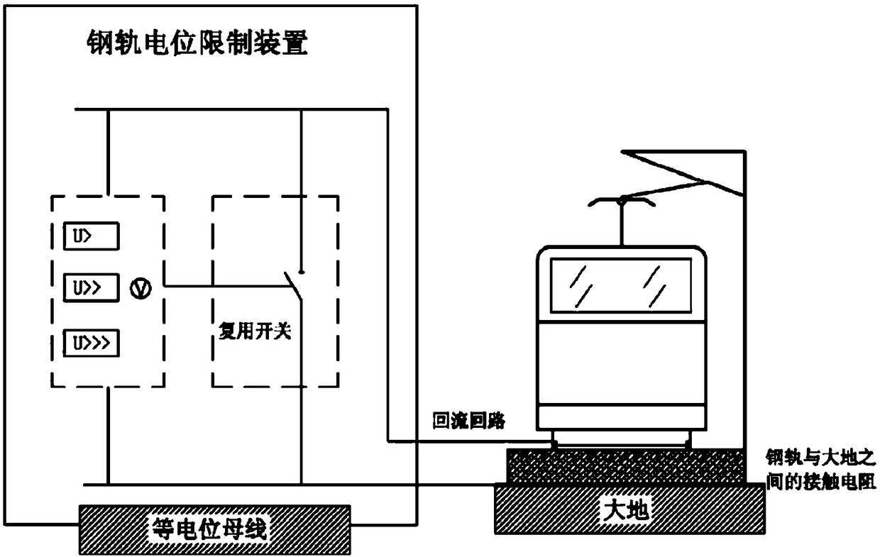
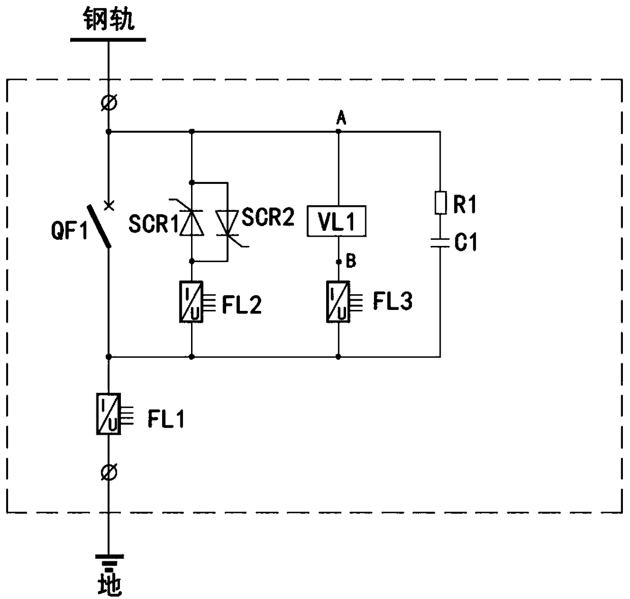
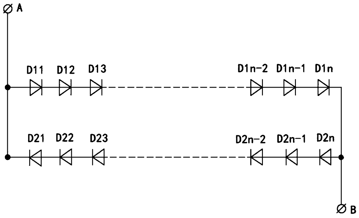
[0052] The specific implementation of the present invention will be further described below in conjunction with the accompanying drawings. The interpretation of each label in the figure is: load switch QF1, the first shunt FL1, the second shunt FL2, the third shunt FL3, the first thyristor SCR1, the first shunt Second thyristor SCR2, third thyristor SCR3, voltage limiting module VL1, first resistor R1, second resistor R2, third resistor R3, first capacitor C1, second capacitor C2, insulated gate bipolar transistor IGBT, first two Diode D1, second diode D2, third diode D3, fourth diode D4, fifth diode D5, first rectification module MV1, second rectification module MV2.

[0053] The invention adopts power electronics and microcomputer control technology, and is developed by high-power power electronic devices. The main circuit adopts multiple groups of thyristors, insulated gate bipolar transistors (IGBTs (Insulated Gate Bipolar Transistor) and diodes for series and parallel conn...


PUM


Abstract

The invention provides a novel rail potential limiting device using power electronics and microcomputer control technology, with the development of high-power power electronic devices, the main circuit adopts multiple thyristors, IGBT, series-parallel connection of diodes, the intelligent rail potential measuring and controlling device is used to control the thyristor and the IGBT to realize the intelligent input or output of the voltage limiting branch circuit, The rail potential limiting function of automatically limiting voltage and current when rail potential rises and automatically turning off when rail potential drops can not only ensure the safety of human body and equipment, but also greatly reduce the total stray current leakage through OVPD equipment, and effectively improve theprotection effect of stray current in metro.

Description

technical field [0001] The invention relates to a conductive or insulating device arranged along the running track or at its junction, and in particular relates to a new rail potential limiting device. Background technique [0002] Rail potential limiting device——Rail over-voltage protection device (hereinafter referred to as OVPD) is a key component of the traction operation system of urban rail trains. It is related to the operation safety of the traction power supply system and the safety of staff and passengers. The main measures to prevent the rail potential from being too high. At present, OVPDs are installed in station substations and parking lots / depots of all subway lines across the country. [0003] The OVPD is set between the rail and the protection ground, and is disconnected under normal operating conditions. At present, the OVPD put into use in domestic subways generally adopts a three-stage setting: Stage I: When the detected potential difference reaches the...

Claims


Application Information

Patent Timeline
IPC IPC(8): H02H9/04H02H9/02
CPCH02H9/02H02H9/045
Inventor 黎兴源黄珂田科王益王恕恒
Owner CHENGDU ZHONGGONG ELECTRIC ENG
Why Eureka
Try Eureka