
Device and method for detecting air tightness of casing of automobile reducer

A technology of airtight detection and reducer, which is applied in the direction of liquid tightness measurement by using liquid/vacuum degree, and by measuring the increase and deceleration rate of the fluid, etc., which can solve the problems of inability to realize automatic operation, high requirements for workers' sense of responsibility, and inability to read Leakage and other issues, to achieve the effect of easy computer communication, high degree of automation, high application rate

Pending Publication Date: 2018-12-21
青岛华瑞汽车零部件股份有限公司
View PDF0 Cites 4 Cited by
  • Summary
  • Abstract
  • Description
  • Claims
  • Application Information

AI Technical Summary

Problems solved by technology

However, the above-mentioned detection method has the following defects: large areas of shell reduction are in contact with water, and local water is prone to cause rust; it is impossible to realize the automatic operation of the whole process, and the operation process requires high responsibility of workers, and the risk of false detection is high; labor intensity is high, especially The working environment is very poor in winter; the specific value of the leakage cannot be read, and it is not easy to analyze the cause of the leakage of the shell

Method used


Image

  • Device and method for detecting air tightness of casing of automobile reducer
  • Device and method for detecting air tightness of casing of automobile reducer
  • Device and method for detecting air tightness of casing of automobile reducer

Examples


specific Embodiment approach

[0038] DETAILED DESCRIPTION OF THE PREFERRED EMBODIMENTS The present invention will be further described below in conjunction with the drawings and specific embodiments.

[0039]The invention provides an airtight detection device for an automobile reducer housing, which seals the end face (3) of the oil seal hole (3) at the upper end of the reducer housing (1) and the lower end flange surface (4) and prevents casting defects of the reducer housing (1) A series of processes, such as detection, are automatically controlled by the PLC control system.

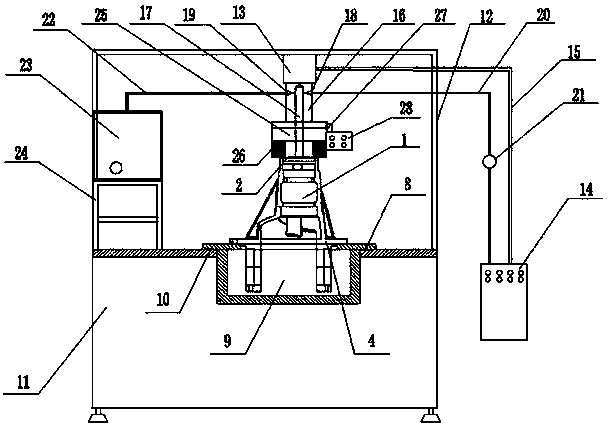
[0040] like image 3 , Figure 4 As shown, the present invention includes a press device, an upper sealing device, a lower sealing device, an air supply system, a low-pressure leak detection system, and a main control system. The press device includes a press frame (12) and a cylinder (13), and the press frame (12) is fixed on the equipment platform (8) with bolts, and the cylinder (13) is fixed on the upper part of the press fra...


PUM


Abstract

A device for detecting air tightness of a casing of an automobile reducer comprises a press device, an upper sealing device, a lower sealing device, a gas supply system, a low-pressure leak detectingsystem, a main control system, an extension rod and a pressure head, wherein the extension rod is connected with a piston rod of a cylinder, an axial blind hole is drilled in the center of the extension rod, two radial holes of a compressed air inlet hole and a low-pressure leaking instrument connecting hole that are communicated with the blind hole are drilled on the rod part of the extension rod, the pressure head is fixed on a flange plate at the lower end of the extension rod by a bolt, a through hole for passing of the compressed air is opened in the center of the pressure head, a ring slot at the lower end of the pressure head is sleeved with a sealing ring, the ring slot is sealed with the end face of an oil sealing hole at the upper end of the casing of the reducer under the pressure of the cylinder, the lower sealing device is installed at the central opening of the equipment platform and is a barrel-shaped sealing cylinder, the upper end of the cylinder body is open and sealed with the flange surface at the lower end of the casing of the reducer, and the lower sealing cylinder includes an O-shaped sealing cylinder and a narrow circular micro-bump sealing cylinder. A device for detecting air tightness of a casing of an automobile reducer provided by the invention has stable and reliable sealing performance, and high applicability, and only needs to replace the pressurehead and the sealing cylinder to check casings of different reducers, thereby saving production and use costs.

Description

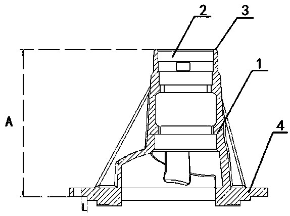
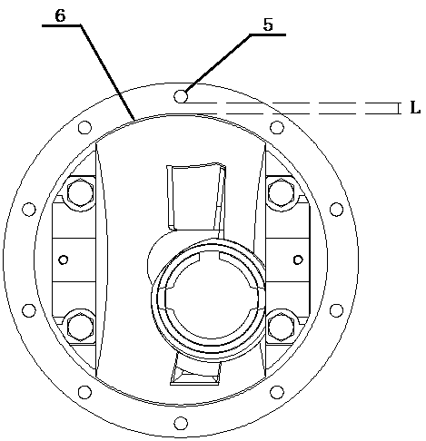
technical field [0001] The invention relates to the field of quality detection of auto parts, in particular to an air-tight detection device and a detection method for an automobile reducer housing. Background technique [0002] figure 1 , figure 2 It is a structural schematic diagram of an existing automobile reducer housing. Due to the different casting process and environment, there may be penetrating cavities and microcracks in the automobile reducer housing after processing. The internal sealing of the drive axle is poor, so the lubricating oil in the drive axle is easy to leak out through the penetrating cavity or micro cracks, affecting the function of the reducer, making it difficult to use the vehicle, increasing the cost of the vehicle, and causing economic losses. Serious oil leakage will pose a threat to the safe operation of the vehicle and lead to accidents. Therefore, the airtightness test of the reducer housing is required before loading. [0003] Exist...

Claims


Application Information

Patent Timeline
Patent Type & Authority Applications(China)
IPC IPC(8): G01M3/32
CPCG01M3/32
Inventor 夏波王海峰刘蒙宋立军李超姚亮位坤刁玉臣魏金宝张学先李武王晓东迟民李传英袁利功王忠生白莎
Owner 青岛华瑞汽车零部件股份有限公司
Learn More