
Vehicle Lamps

A technology for lamps and vehicles, which is applied to vehicle components, lighting and heating equipment, transportation and packaging, etc., can solve problems such as rising manufacturing costs, and achieve the effects of suppressing manufacturing costs and preventing noise

Active Publication Date: 2021-11-26
KOITO MFG CO LTD
View PDF20 Cites 0 Cited by
  • Summary
  • Abstract
  • Description
  • Claims
  • Application Information

AI Technical Summary

Problems solved by technology

Therefore, a process of attaching the protector to the periphery of the lens front surface portion by bonding is required, which increases the manufacturing cost.

Method used


Image

  • Vehicle Lamps
  • Vehicle Lamps
  • Vehicle Lamps

Examples


Embodiment 1

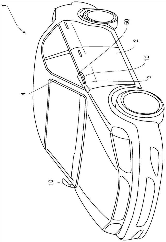
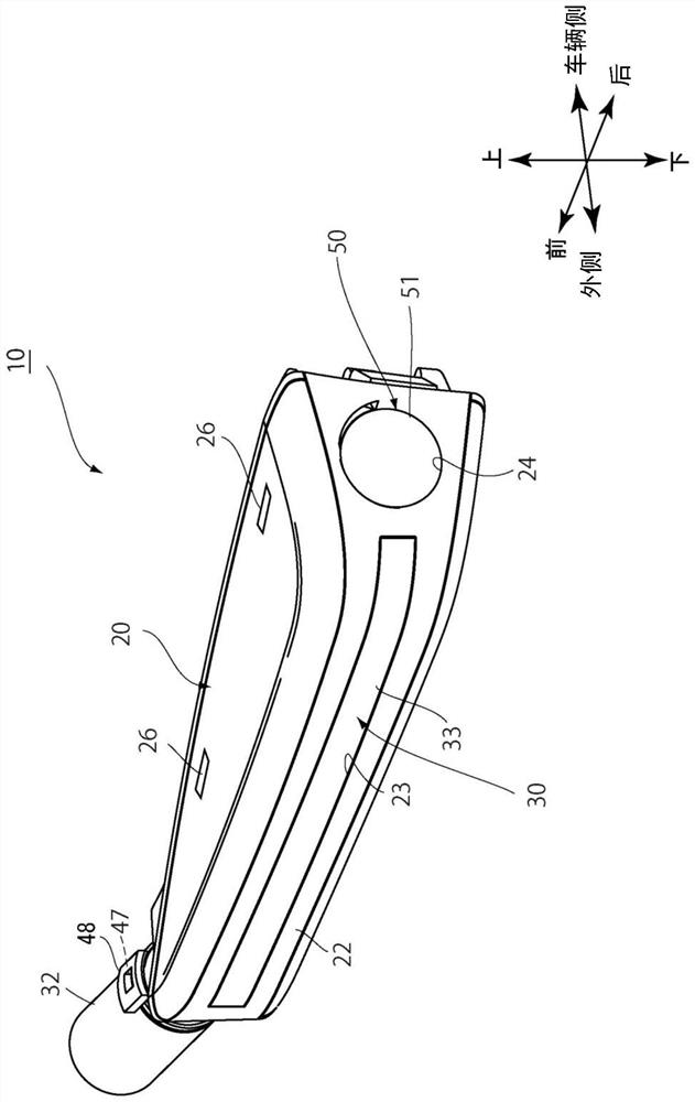
[0043] figure 1 It is a perspective view of a vehicle 1 equipped with the vehicle lamp 10 according to the first embodiment. The vehicle lamp 10 is a side turn signal lamp arranged at the base of the front pillar 4 at the waistline 3 of the left and right front side doors 2 of the vehicle. The left and right vehicular lamps 10 are configured symmetrically with respect to the axis in the front-rear direction of the vehicle. Therefore, only the left vehicular lamp 10 will be described below and the description of the right vehicular lamp will be omitted.

[0044] figure 1 The illustrated vehicle 1 is equipped with electronic mirrors instead of conventional fender mirrors and door mirrors. This electronic mirror is configured to include a display and a camera 50 . The camera 50 is mounted on the vehicle lamp 10, and the display (not shown) is installed in the vehicle at a position where the driver can visually recognize it. The display displays image information acquired by...

Embodiment 2

[0068] The vehicle lighting device 100 according to the second embodiment has the lamp unit 30 in the vehicle lighting device 10 of the first embodiment, specifically, the light emitting part 33 , the main body 34 and the contact part 35 in a configuration described later. The other configurations are the same as those of the vehicle lamp 10 of the first embodiment, and therefore, the same components are given the same reference numerals and their descriptions are omitted.

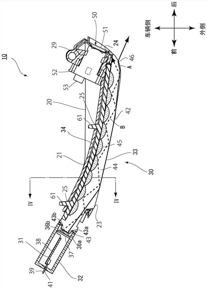
[0069] Figure 6 is with Figure 4 The illustrated vehicular lamp 10 is a cross-sectional view of a cutaway portion of the vehicular lamp 100 according to the second embodiment in the same manner.

[0070] The light emitting unit 133 is formed of, for example, a light guide lens made of acrylic resin. The cross section of the main body 133 a of the light emitting part 133 is formed into a trapezoid, and the outer surface 142 of the main body 133 a of the light emitting part 133 is formed into a rectangle...


PUM


Abstract

The present invention provides a vehicle lamp capable of preventing noise caused by vibration and wind noise while suppressing manufacturing cost. A vehicle lamp (10) is characterized by comprising: a housing (20) having an opening (23); a light emitting unit (33) housed in the housing (20) , and exposed from the opening (23) toward the outside of the housing (20); the light source (36a, 36b), the light source (36a, 36b) is arranged near the light incident end (43) of the light emitting part; the main body ( 34), the main body (34) supports the above-mentioned light-emitting part; and the contact part (35), the contact part (35) is arranged along the side of the above-mentioned light-emitting part (33), and is connected to the above-mentioned casing (20 ) in contact with the inner wall (28) to support the housing (20), the abutment portion (35) is flexible, and the abutment portion (35) is in contact with the main body (34) or the abutment portion (35) ) integrally formed.

Description

technical field [0001] The present invention relates to a vehicle lamp, and more specifically, to a vehicle lamp having a light emitting portion exposed from an opening of a case. Background technique [0002] Conventionally, as disclosed in Patent Document 1, there has been proposed a side turn signal lamp configured to provide an opening in a side reflector housing, expose a light guide lens through the opening, and function as a light emitting unit. [0003] However, in the side turn signal lamp of Patent Document 1, it is necessary to prevent the side reflector housing and the light guide lens from directly colliding with each other to generate noise due to vibration, or to generate wind noise due to a gap generated between the two. Between the flange portion of the lens and the inner wall around the opening of the housing, a protector made of elastic materials such as sponge and rubber is provided as other components (refer to paragraph 0033, Figure 5 ). Therefore, a ...

Claims


Application Information

Patent Timeline
Patent Type & Authority Patents(China)
IPC IPC(8): F21S43/19F21S45/10F21V19/00F21W103/20
CPCF21S43/19F21S45/10F21V19/00F21W2103/20F21W2103/25F21S43/237F21S43/245
Inventor 风冈成彦
Owner KOITO MFG CO LTD
Learn More