
A marine vibration damping paddle shaft

A propeller shaft and vibrating propeller technology, applied in the field of vibration reduction and noise reduction, can solve the problems of reducing the use accuracy, wear of parts, damage to the propeller, etc., and achieve the effect of inhibiting the transmission of vibration

Active Publication Date: 2018-12-21
HARBIN ENG UNIV
View PDF5 Cites 4 Cited by
  • Summary
  • Abstract
  • Description
  • Claims
  • Application Information

AI Technical Summary

Problems solved by technology

[0003] The main hazards of severe vibration to ships are as follows: 1. Cause fatigue damage to the hull structure or mechanical equipment when the stress is too large, affecting navigation safety; 2. Affect the living comfort of the crew and passengers, and affect the work efficiency of the crew. Harmful to health
3. Affect the normal operation of equipment and instruments on board, reduce the accuracy of use, and shorten the service life
2. Problems in construction quality, such as poor manufacturing quality of propellers, poor axis alignment, damage to structural continuity, welding residual stress and initial deflection, etc.
3. Operational management problems, such as improper loading (ballasting) of the hull, deformation of the shaft system, uneven combustion of each cylinder of the main engine, wear and tear of machine parts, damage to the propeller, etc.
There are several measures to reduce vibration: (1) The excitation frequency of the propeller is similar to the local natural frequency of the hull. When resonance is formed, the local structure of the hull can be strengthened and the local natural frequency can be changed. girders, etc.; (2) uneven flow from the propeller, resulting in greater vibration of the propeller
At present, there is no effective shafting vibration control technology

Method used


Image

  • A marine vibration damping paddle shaft
  • A marine vibration damping paddle shaft
  • A marine vibration damping paddle shaft

Examples


Embodiment Construction

[0026] The present invention is described in more detail below in conjunction with accompanying drawing:

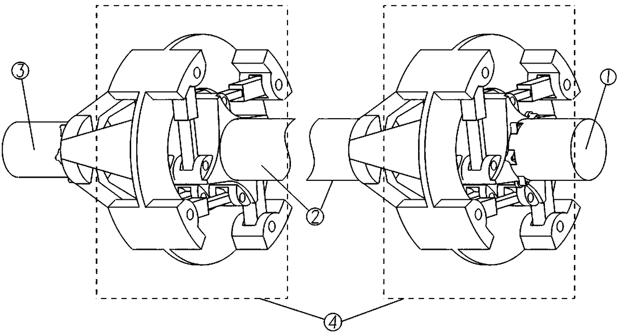
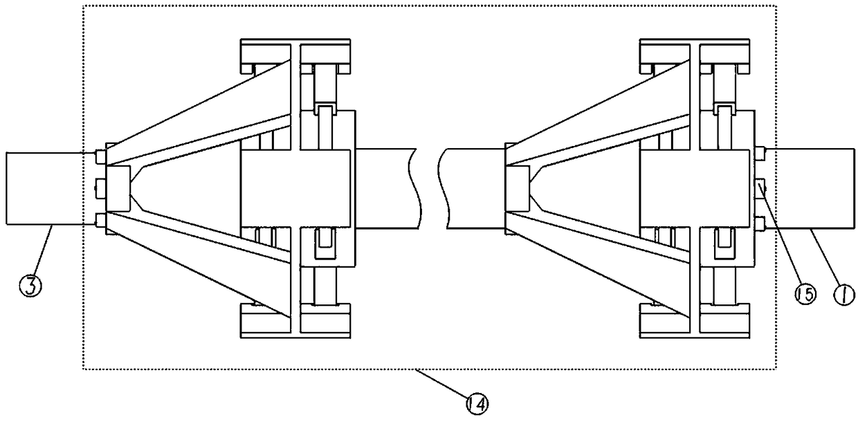
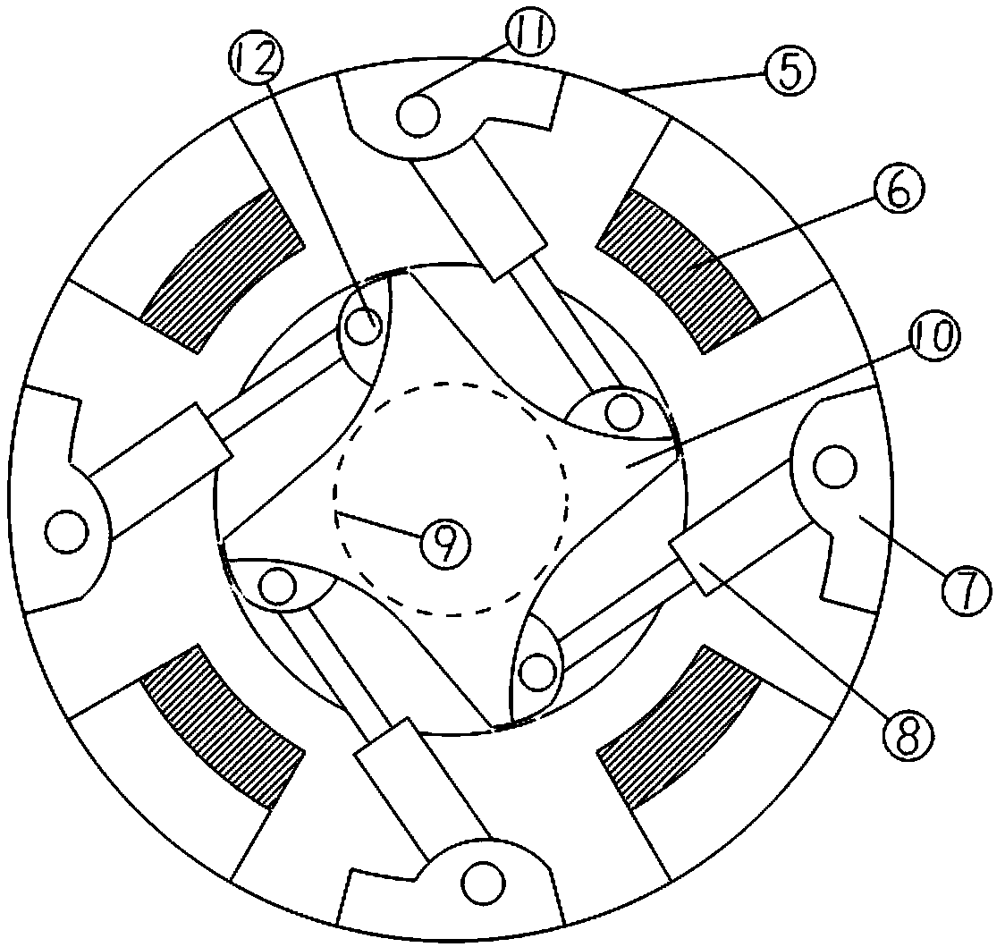
[0027] combine figure 1 , 2 , 3, 4, 5, 6, the working principle of the marine damping propeller shaft is:

[0028] The marine propeller shaft is divided into three sections: the front part of the propeller shaft 1, the middle part of the propeller shaft 2, and the end part of the propeller shaft 3. The length of the middle part of the propeller shaft 2 accounts for the main part of the total length of the propeller shaft. A vibration damping mechanism is connected to one end of the middle section of the paddle shaft, and the other end of the middle section of the paddle shaft is connected to the end section of the paddle shaft through a second vibration damping mechanism, and the front section of the paddle shaft, the middle section of the paddle shaft, the end section of the paddle shaft and the two vibration damping mechanisms rotate simultaneously;

[0029] The stato...


PUM


Abstract

The invention discloses a marine vibration damping paddle shaft, belonging to the field of vibration damping and noise reduction. The damping paddle shaft includes a forward paddle shaft directly connected to the main engine or gearbox of the ship, a first damping mechanism, a middle paddle shaft, a second damping mechanism, and a terminal paddle shaft. Firstly, the traditional single propeller shaft is separated into three sections, the middle length of the shaft is the main part of the total length of the shaft, the forepart propeller shaft is directly connected with the main engine or gearbox of the ship, The terminal shaft is connected with the propeller or the steering conversion device, and the middle shaft is connected with the other two shafts through the vibration damping device,that is, the vibration source is isolated, the vibration is absorbed, the vibration of the main engine and the gear box of the ship and the vibration of the propeller are restrained and transmitted tothe middle section of the propeller shaft, and the shafting vibration and the hull vibration are reduced. Sixteen shock absorbers in the damping mechanism transmit shaft torque through springs, and absorb vibration through the joint action of springs and damping fluid, so as to suppress vibration transmission to the middle section of the shaft, which occupies the main part of the shaft length, thereby reducing the vibration response of the shaft system and the ship hull.

Description

technical field [0001] The invention relates to a vibration-damping paddle shaft for ships, which belongs to the field of vibration-damping and noise-reducing. Background technique [0002] As early as the late 19th century, the problem of hull vibration began to attract people's attention. In recent years, with the development of the shipping industry, the power and speed of the main engine have increased, the tonnage of the ship has increased, and the emergence of fat ships has caused the problem of hull vibration to become increasingly prominent. With the advancement of shipbuilding technology, the hull structure is lightened, and the structural rigidity is also reduced, which is more likely to arouse large hull vibrations. [0003] The main hazards of severe vibration to ships are as follows: 1. Cause fatigue damage to the hull structure or mechanical equipment when the stress is too large, affecting navigation safety; 2. Affect the living comfort of the crew and passen...

Claims


Application Information

Patent Timeline
Patent Type & Authority Applications(China)
IPC IPC(8): B63H23/34
CPCB63H23/34
Inventor 胡健王英铸巨浩天毛翼轩陈昉张维鹏孙士丽苏维明陈宇航刘立超
Owner HARBIN ENG UNIV
Learn More