
Air-conditioning unit

A technology for air conditioning devices and heat exchangers, which is applied in the directions of heat exchange equipment safety devices, space heating and ventilation, space heating and ventilation details, etc.

Active Publication Date: 2006-09-06
DENSO CORP
View PDF0 Cites 0 Cited by
  • Summary
  • Abstract
  • Description
  • Claims
  • Application Information

AI Technical Summary

Problems solved by technology

However, the disadvantage of this structure is that the condensed water w is easy to adhere to the cylindrical part of the casing 25 located in the casing 11, and because the water moves along the surface of the casing 25, it leaks from the casing 11 through the fitting hole 15.

Method used


Image

  • Air-conditioning unit
  • Air-conditioning unit
  • Air-conditioning unit

Examples


Embodiment Construction

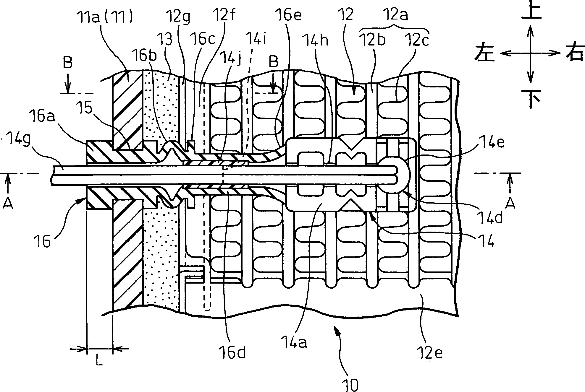
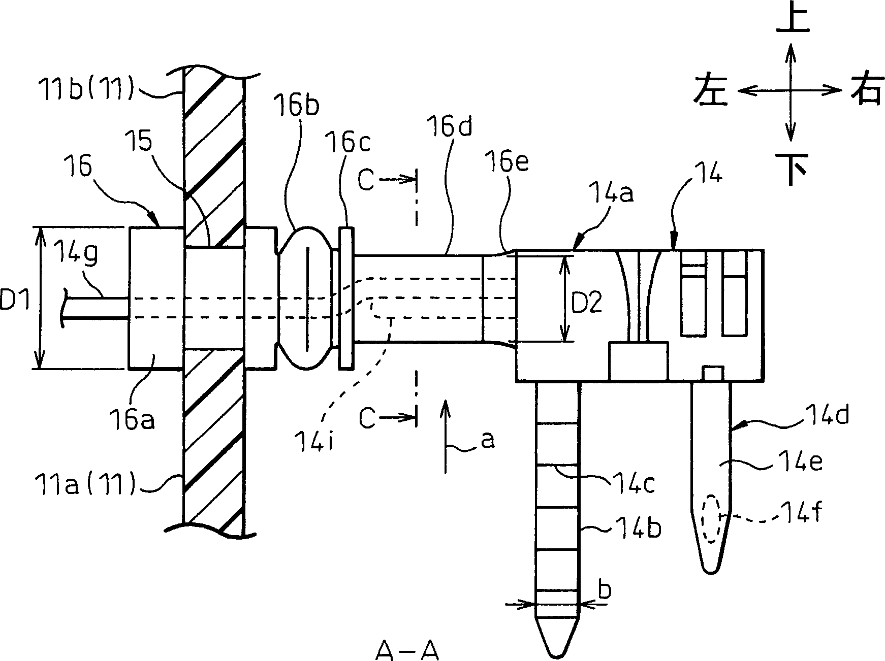
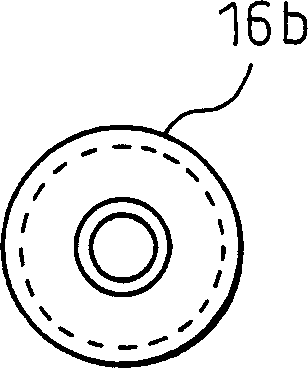
[0061] Embodiments of the present invention are described with reference to the drawings. figure 1 is a sectional view showing the main part of the air conditioner 10 using the structure of the sensor assembly according to the present invention. Figure 2A is shown along figure 1 A cross-sectional view of the middle line A-A. Figure 2B is showing Figure 2A Front view of sleeve bellows shown. image 3 is shown along Figure 2A Sectional view of the middle line C-C. figure 1 , 2A The vertical, horizontal, and longitudinal directions in correspond to the vertical, horizontal, and longitudinal directions of the vehicle.

[0062] The casing 11 of the air conditioner 10 has two functions, on the one hand, it is to form an air channel for the conditioned air; door (not shown). The case 11 is formed of resin, and is divided into a plurality of division cases 11a, 11b in order to facilitate release of the resin molding die and assembly of accommodated devices. The mating ...


PUM


Abstract

An air-conditioning unit, in which at least a lead wire ( 14 g) of a temperature sensor ( 14 ) is inserted in a cylindrically formed grommet ( 16 ), is disclosed. A cylindrical seal portion ( 16 a) fitted in a hole portion ( 15 ) of a case ( 11 ) is formed at an end of the grommet ( 16 ). The lead wire ( 14 g) is fitted relatively displaceably on the inner periphery of the cylindrical seal portion ( 16 a). A cylindrical fixed portion ( 16 d) fixed with the lead wire ( 14 g) is formed at the other end of the grommet ( 16 ). A bellows ( 16 b) is formed between the cylindrical seal portion ( 16 a) and the cylindrical fixed portion ( 16 d).

Description

technical field [0001] The present invention relates to a sensor assembly structure for an air-conditioning device having an evaporator or similar heat exchanger constructed therein, and more particularly to a sensor assembly structure for an air-conditioning system for vehicles. Background technique [0002] In recent years, demands for improving quietness in the vehicle interior have increased, and air-conditioning systems for vehicles employ a structure in which a heat exchanger such as an evaporator is floatingly supported with respect to a housing of the air-conditioning apparatus via a buffer. [0003] Figure 5 A sketch of the prior art for supporting a heat exchanger in a floating position is shown. This structure includes a buffer member 13 disposed between the evaporator 12 constituting a heat exchanger for cooling operation and the inner wall surface of the air conditioner housing 11. The cushioning member 13 is made of a flexible material such as foamed resin. ...

Claims


Application Information

Patent Timeline
Patent Type & Authority Applications(China)
IPC IPC(8): F24F11/02F24F13/30
CPCF25B39/02F28F2265/30
Inventor 白石浩明臼井和男杉浦孝直
Owner DENSO CORP
Learn More