Temperature detection device used in severe environment
A technology for harsh environments and detection devices, applied in measuring devices, thermometers, thermometers with physical/chemical changes, etc., can solve the problems of signal phase-frequency characteristics, unfavorable optical fiber sensors, and difficult to filter clean, etc., to achieve phase The detection error is small, the application is wide, and the work is reliable.
- Summary
- Abstract
- Description
- Claims
- Application Information
AI Technical Summary
Problems solved by technology
Method used
Image

Examples
Embodiment 1
[0028] Embodiment 1 Overall structure of the present invention
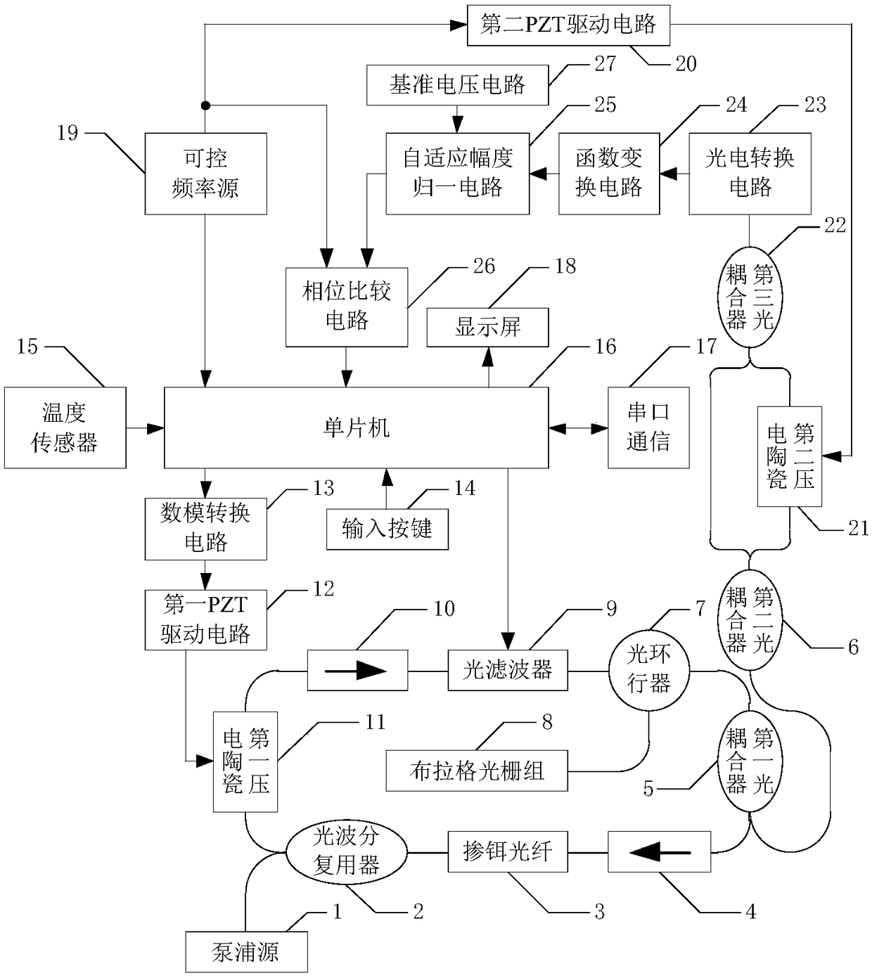
[0029] like figure 1 As shown, the overall structure of the present invention has, the pump source 1 (980nm laser, maximum output power is 1W) is connected with the 980nm end of the optical wavelength division multiplexer 2 (980 / 1550nm wavelength division multiplexer), and the optical wavelength division multiplexer The 1550nm end of device 2 is connected with one end of the optical fiber wound on the first piezoelectric ceramic 11 (cylindrical piezoelectric ceramic, outer diameter 50mm, inner diameter 40mm, height 50mm), and the optical fiber wound on the first piezoelectric ceramic 11 The other end is connected to the input end of the first optical isolator 10 (1550nm polarization-independent optical isolator), and the control end of the first piezoelectric ceramic 11 is connected to the first PZT drive circuit 12 (device made by our research group, see patent for specific structure. ZL200710055865.8) is conne...
Embodiment 2
[0031] Embodiment 2 function conversion circuit
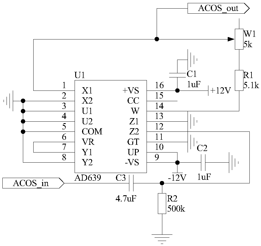
[0032] The structure of the function conversion circuit 24 is as follows: one end of the capacitor C3 is connected to the pin 12 of the trigonometric function converter U1 and one end of the resistor R2, and the other end of the capacitor C3 is used as the input terminal of the function conversion circuit 24, which is recorded as the port ACOS_in , connected to the output end of the photoelectric conversion circuit 23; the other end of the resistor R2 is grounded; the pins 2, 3, 4, 5, 8, 11, 13 of the trigonometric function converter U1 are grounded, and the pins 9, 10 are connected to the capacitor C2 One end is connected to -12V power supply, the other end of capacitor C2 is grounded; pin 6 of trigonometric function converter U1 is connected to pin 7, pin 16 is connected to +12V power supply and one end of capacitor C1, and the other end of capacitor C1 is grounded; The pin 1 of the trigonometric function converter U1 is conn...
Embodiment 3
[0033]Embodiment 3 Adaptive Amplitude Normalization Circuit
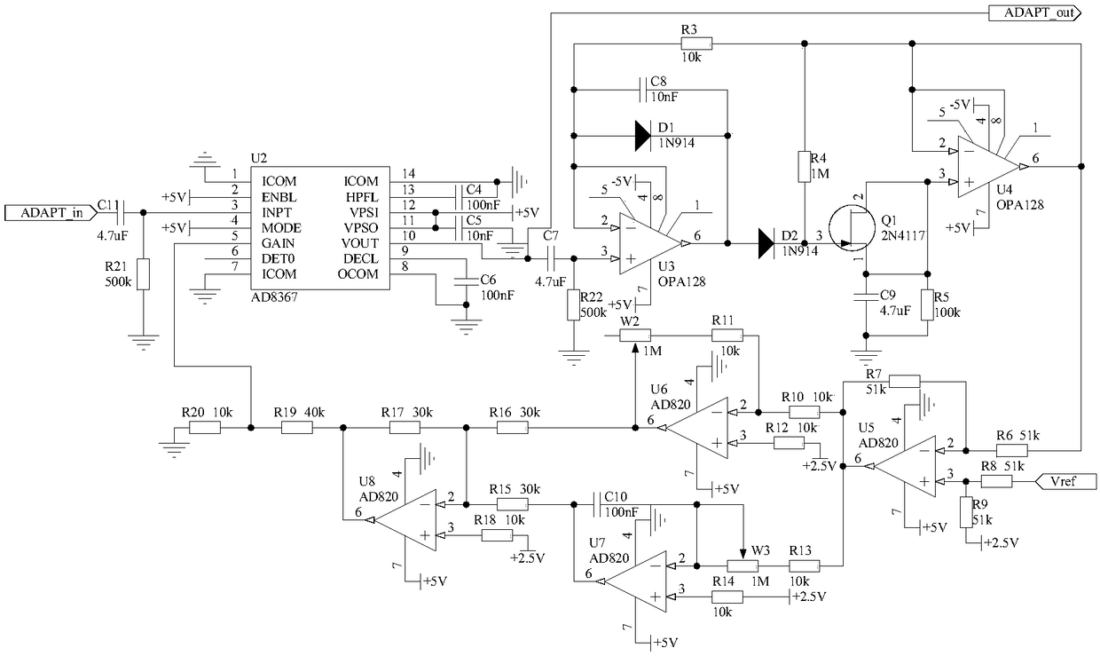
[0034] Because the amplitude of the signal output by the function conversion circuit 24 is small, and is affected by multiple parameters in the optical path and the circuit, the size is indefinite, so the present invention designs an adaptive amplitude normalization circuit 25, which is used to convert the signal output by the function conversion circuit 24 The amplitude is normalized to the optimal size to further improve the accuracy of demodulation. The structure of the adaptive amplitude normalization circuit 25 is that one end of the capacitor C11 is connected to one end of the resistor R21 and the pin 3 of the chip U2, the other end of the resistor R21 is grounded, and the other end of the capacitor C11 is used as an adaptive amplitude normalization The input end of the circuit 25 is recorded as the port ADAPT_in, which is connected with the port ACOS_out of the function transformation circuit 24; the pin 1, t...
PUM
| Property | Measurement | Unit |
|---|---|---|
| wavelength | aaaaa | aaaaa |
| reflectance | aaaaa | aaaaa |
Abstract
Description
Claims
Application Information
 - R&D
- Intellectual Property
- Life Sciences
- Materials
- Tech Scout
- Unparalleled Data Quality
- Higher Quality Content
- 60% Fewer Hallucinations
Browse by: Latest US Patents, China's latest patents, Technical Efficacy Thesaurus, Application Domain, Technology Topic, Popular Technical Reports.
© 2025 PatSnap. All rights reserved.Legal|Privacy policy|Modern Slavery Act Transparency Statement|Sitemap|About US| Contact US: help@patsnap.com