Fiber sensor based on Michelson interference
An optical fiber sensor and optical coupler technology, which is applied in the direction of using optical devices to transmit sensing components, can solve the problems of variable frequency, difficult to filter clean, unfavorable optical fiber sensors, etc., and achieves the effect of reliable operation.
- Summary
- Abstract
- Description
- Claims
- Application Information
AI Technical Summary
Problems solved by technology
Method used
Image


Examples
Embodiment 1
[0028] Embodiment 1 Overall structure of the present invention
[0029] Such as figure 1 As shown, the overall structure of the present invention has, pumping source 1 (VENUS series 980nm high-power single-mode pumping light source of Shanghai Knet Laser Technology Co., Ltd., the model is VLSS-980-B, and the maximum single-mode output optical power is The output end of 1200mW) is connected to the input end of the first optocoupler 2 (produced by OZ-OPTICS company, model is FUSED-12-1064-7 / 125-90 / 10-3U-3mm, splitting ratio is 90:10) , one output end of the first optical coupler is connected with the 980nm end of the optical wavelength division multiplexer 3 (the fusion tapered 980 / 1550nm pump optical wavelength division multiplexing coupler produced by Shanghai Hanyu Optical Fiber Communication Technology Co., Ltd.), and the optical wave The 1550nm end of the demultiplexer 3 is connected to one end of an optical fiber wound on the first piezoelectric ceramic 12 (cylindrical p...
Embodiment 2
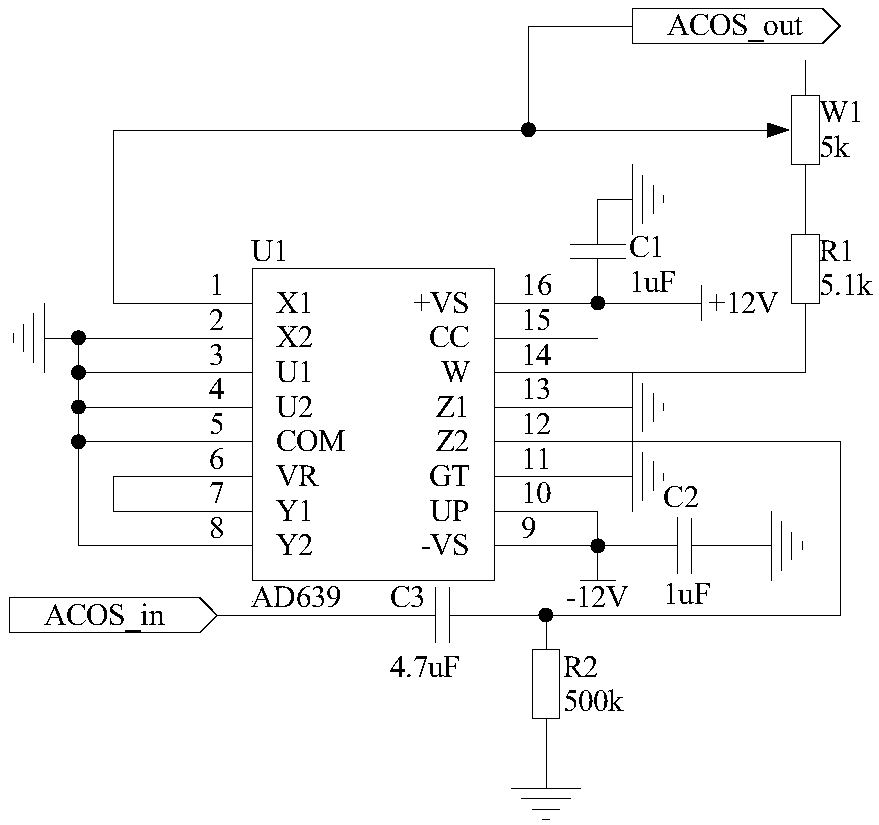
[0031] Embodiment 2 function transformation circuit
[0032]The structure of the function conversion circuit 29 is that one end of the capacitor C3 is connected to the pin 12 of the trigonometric function converter U1 and one end of the resistor R2, and the other end of the capacitor C3 is used as the input terminal of the function conversion circuit 29, which is denoted as the port ACOS_in , is connected with the output end of the second photoelectric conversion circuit 28; the other end of the resistor R2 is grounded; the pins 2, 3, 4, 5, 8, 11, 13 of the trigonometric function converter U1 are grounded, and the pins 9, 10 are connected to the capacitor One end of C2 is connected to -12V power supply, the other end of capacitor C2 is grounded; pin 6 of trigonometric function converter U1 is connected to pin 7, pin 16 is connected to +12V power supply and one end of capacitor C1, and the other end of capacitor C1 Grounding; pin 1 of the trigonometric function converter U1 is ...
Embodiment 3
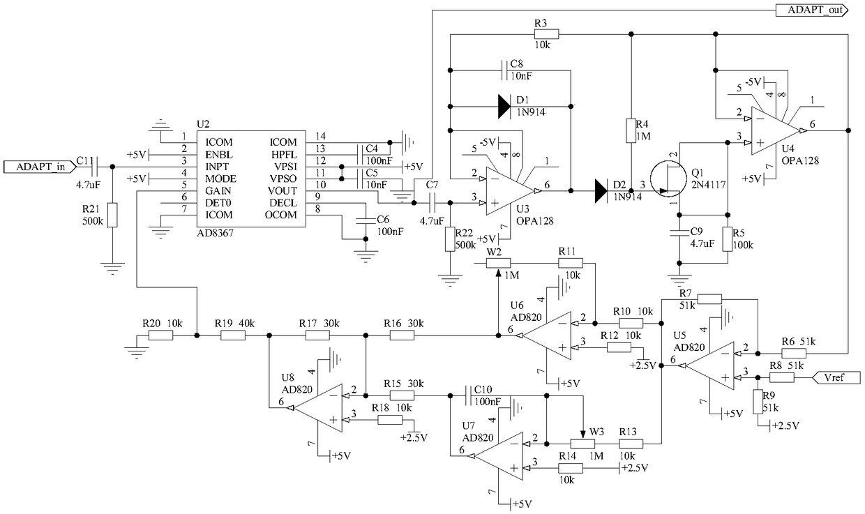
[0033] Embodiment 3 Adaptive Amplitude Normalization Circuit
[0034] Because the amplitude of the signal output by the function conversion circuit 29 is relatively small, and is affected by multiple parameters in the optical path and the circuit, the size is indefinite, so the present invention designs an adaptive amplitude normalization circuit 30, which is used to convert the signal output by the function conversion circuit 29 The amplitude is normalized to the optimal size to further improve the accuracy of demodulation. The specific structure is that one end of the capacitor C11 is connected to one end of the resistor R21 and the pin 3 of the chip U2, the other end of the resistor R21 is grounded, and the other end of the capacitor C11 is used as the input end of the adaptive amplitude normalization circuit 30, which is recorded as the port ADAPT_in , is connected with the port ACOS_out of the function conversion circuit 29; the pin 1, the pin 7, the pin 8 and the pin 14 ...
PUM
 Abstract
Description
Claims
Application Information
 - R&D
- Intellectual Property
- Life Sciences
- Materials
- Tech Scout
- Unparalleled Data Quality
- Higher Quality Content
- 60% Fewer Hallucinations
Browse by: Latest US Patents, China's latest patents, Technical Efficacy Thesaurus, Application Domain, Technology Topic, Popular Technical Reports.
© 2025 PatSnap. All rights reserved.Legal|Privacy policy|Modern Slavery Act Transparency Statement|Sitemap|About US| Contact US: help@patsnap.com