
Multifunctional grain drying machine

A grain dryer, multi-functional technology, applied in dryers, drying, grain drying and other directions, can solve the problems of single drying method, single function, increase the cost of grain storage, etc., and achieve the effect of convenient manual operation

Inactive Publication Date: 2018-12-18
ANHUI SUNMIRO AGRI TECH
View PDF9 Cites 3 Cited by
  • Summary
  • Abstract
  • Description
  • Claims
  • Application Information

AI Technical Summary

Problems solved by technology

[0002] With the improvement of grain varieties and the increase of yield per unit area, my country's agriculture has increased production and income again and again, and the problem of grain storage has become more and more prominent. Carry out drying operation to prevent mildew and other problems in the subsequent storage process of the grain, but the existing grain dryer has a relatively simple structure and a relatively single function, which can only achieve the drying effect, and the drying method It is also relatively simple, and before drying some new grains, it is necessary to clean up impurities or poor-quality grains in the new grains to improve the quality of the stored grains, but these screening processes often require other equipment for special processing, invisible The cost of grain storage is increased, and the grain needs to be transported multiple times, which wastes a lot of manpower and material resources and reduces the drying efficiency.

Method used


Image

  • Multifunctional grain drying machine
  • Multifunctional grain drying machine
  • Multifunctional grain drying machine

Examples


Embodiment Construction

[0014] The following will clearly and completely describe the technical solutions in the embodiments of the present invention with reference to the accompanying drawings in the embodiments of the present invention. Obviously, the described embodiments are only some, not all, embodiments of the present invention. Based on the embodiments of the present invention, all other embodiments obtained by persons of ordinary skill in the art without making creative efforts belong to the protection scope of the present invention.

[0015] In the description of the present invention, it should be noted that the terms "upper", "lower", "inner", "outer", "front end", "rear end", "both ends", "one end", "another end" The orientation or positional relationship indicated by etc. is based on the orientation or positional relationship shown in the drawings, and is only for the convenience of describing the present invention and simplifying the description, rather than indicating or implying that ...


PUM


Abstract

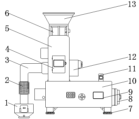
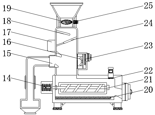
The invention discloses a multifunctional grain drying machine. The multifunctional grain drying machine comprises a residue discharge pipe, a screening shell and a drying drum. A rotation motor is mounted on the surface of one side of the drying drum. A drying cavity is mounted in the drying drum. A first constant-temperature heating plate is mounted in the position, below the drying cavity, of the interior of the drying drum. An air blasting shell is mounted on the surface of one side of the screening shell. An exhaust net drum is mounted on the surface of the residue discharge pipe. The bottom end of the residue discharge pipe is provided with an accumulation shell. A conveying shell is mounted at the top end of the screening shell. The surface of the conveying shell is provided with anon-off motor. An on-off valve plate is mounted in the conveying shell. A feed hopper is welded to the top end of the conveying shell. Through arrangement of a series of structures, the multifunctional grain drying machine can control the flow velocity of grains in the using process, has the impurity removal function and improves the quality of the grains and the drying efficiency.

Description

technical field [0001] The invention relates to the technical field of grain storage, in particular to a multifunctional grain dryer. Background technique [0002] With the improvement of grain varieties and the increase of per unit area yield, my country's agriculture has increased production and income again and again, and the problem of grain storage has become more and more prominent. Drying operation is carried out to prevent problems such as mildew of the grain in the subsequent storage process, but the existing grain dryer has a relatively simple structure and a relatively single function, which can only achieve a drying effect. It is also relatively simple, and before drying some new grains, it is necessary to clean up the impurities or poor-quality grains in the new grains to improve the quality of the stored grains, but these screening processes often require other equipment for special processing, invisible This increases the cost of grain storage, requires multiple...

Claims


Application Information

Patent Timeline
Patent Type & Authority Applications(China)
IPC IPC(8): F26B17/12F26B21/00F26B1/00F26B25/00F26B25/12B07B4/02A23B9/08
CPCF26B17/12A23B9/08B07B4/02F26B1/00F26B21/001F26B25/002F26B25/12F26B2200/06
Inventor 陆必发
Owner ANHUI SUNMIRO AGRI TECH
Learn More