An ejection trajectory device of a launcher

A launcher and orbital technology, which is applied to rocket launchers, launch/drag transmission devices, and lifting devices, etc., can solve the problems of high system cost and complicated operation, and achieves low measurement and control costs, easy welding and construction, and high overall rigidity. Effect

Pending Publication Date: 2018-12-18
QIHANG LAUNCHING TECH CO LTD
View PDF0 Cites 2 Cited by
  • Summary
  • Abstract
  • Description
  • Claims
  • Application Information

AI Technical Summary

Problems solved by technology

[0006] In addition, since the current ejection track device does not have a measuring mechanism, in order to obtain the motion data of the trolley and the UAV during the ejection process, only high-speed cameras, wireless sensors and other additional equipment can be used for measurement and control. The system cost is high and the operation is complicated.

Method used


Image

  • An ejection trajectory device of a launcher
  • An ejection trajectory device of a launcher
  • An ejection trajectory device of a launcher

Examples


Embodiment Construction

[0050] The ejection track device of the launcher of the present invention will be described in detail below with reference to the accompanying drawings.

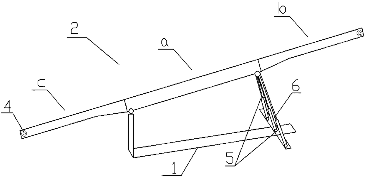
[0051] As shown in Figure 1-14, an ejection track device for a launcher includes a base 1 and a track 2 located on the base 1. The track 2 in this embodiment consists of three sections of tracks, which are respectively a secondary track b and a main track a. Sub-track two c, the rear end of sub-track one b and the front end of main track a are connected together by hinges.

[0052] More specifically: the right rear end of the auxiliary track ab is hingedly connected with the right front end of the main track a. The above structure realizes that the auxiliary track b can be bent and folded to the right, and the folding effect is that the auxiliary track ab Parallel with the main track a to achieve the purpose of retracting. The left rear end of the main track a and the left front end of the secondary track 2 c are connected ...


PUM


Abstract

The invention relates to the launching field of an unmanned aerial vehicle, which is an ejection trajectory device of a launcher. The device Comprises a base and a track located on the base, wherein the track can be assembled into one track or several tracks, and the tracks are folded and retracted laterally or vertically in a hinged manner in the track plane. The above-mentioned rails are mainlyinserted and welded by the alignment of the upper, lower, left and right panels and the rib panels between them. The rear part of the rail is hinged on the base, the two sides of the front part of therail are coaxially hinged with a pair of balancing hydraulic cylinders, and the other ends of the pair of balancing hydraulic cylinders are also coaxially hinged on the two sides of the base. The lifting hydraulic cylinder is hinged on the rail and the base, and the hinge axis of the lifting hydraulic cylinder can be coaxial with or parallel to the hinge axis of the balancing hydraulic cylinder.The invention has the advantages of scientific and reasonable design, assembly, high manufacturing accuracy, light weight, high strength, good stability, low construction cost and easy mass production, and is a technical revolution in the field.

Description

technical field [0001] The invention relates to the field of launching unmanned aerial vehicles, in particular to an ejection track device for a launcher. Background technique [0002] There are many ways for unmanned aerial vehicles to take off, such as rolling, vehicle-mounted, airdrop, hand-throwing, rocket-assisted, and catapult take-off. Catapult take-off is the mainstream of current research at home and abroad. Catapult takeoff is not restricted by factors such as the environment and runways, and can take off anytime and anywhere, with wide applicability. [0003] At present, for large-scale ejection devices, due to the long track length and high launch speed, affected by factors such as wind force and vibration, even a slight swing may cause the deformation and imbalance of the aircraft's off-orbit movement, and severe swings may interfere with the aircraft. It may cause flight and operation accidents. Moreover, during the launching operation of the aircraft, its o...

Claims


Application Information

Patent Timeline
Patent Type & Authority Applications(China)
IPC IPC(8): B64F1/06
CPCB64F1/06B64U70/70B66F3/25F41F3/045A63H27/00B64C39/024
Inventor 毕和军
Owner QIHANG LAUNCHING TECH CO LTD
Why Eureka
Try Eureka