Large thin-wall double-layer cylinder deep hole machining device and machining method thereof

A processing device and double cylinder technology, used in boring/drilling devices, metal processing equipment, manufacturing tools, etc., can solve the problem of affecting inner hole machining, difficulty in ensuring inner hole machining accuracy and surface roughness, and increased machining difficulty, etc. problems, to achieve the effect of reducing the deformation of the cylinder, increasing the stiffness, and reducing the deformation of the cylinder

Active Publication Date: 2020-05-05
TAIZHONG TIANJIN BINHAI HEAVY MACHINERY
View PDF20 Cites 2 Cited by
  • Summary
  • Abstract
  • Description
  • Claims
  • Application Information

AI Technical Summary

Problems solved by technology

[0004] When loading a large thin-walled double-layer cylinder, due to the thin wall of the cylinder, the clamping of the claws and the support of the idler will cause a large deformation of the double-layer cylinder, which will affect the processing of the inner hole; in order to prevent the opening of the cylinder wall from causing the inner hole Deformation, before machining the inner hole, it is necessary to rough the lookout hole and the sensor hole, which causes the machining of the inner hole to be interrupted cutting, which increases the processing difficulty; It is difficult to guarantee the machining accuracy and surface roughness of the inner hole

Method used


Image

  • Large thin-wall double-layer cylinder deep hole machining device and machining method thereof
  • Large thin-wall double-layer cylinder deep hole machining device and machining method thereof
  • Large thin-wall double-layer cylinder deep hole machining device and machining method thereof

Examples


Embodiment Construction

[0058] In order to make the purpose, technical solution and advantages of the present invention clearer, the technical solution of the present invention will be clearly and completely described below in conjunction with specific embodiments of the present invention and corresponding drawings. Apparently, the described embodiments are only some of the embodiments of the present invention, but not all of them. Based on the embodiments of the present invention, all other embodiments obtained by persons of ordinary skill in the art without making creative efforts fall within the protection scope of the present invention.

[0059] The technical solutions provided by the embodiments of the present invention will be described in detail below in conjunction with the accompanying drawings.

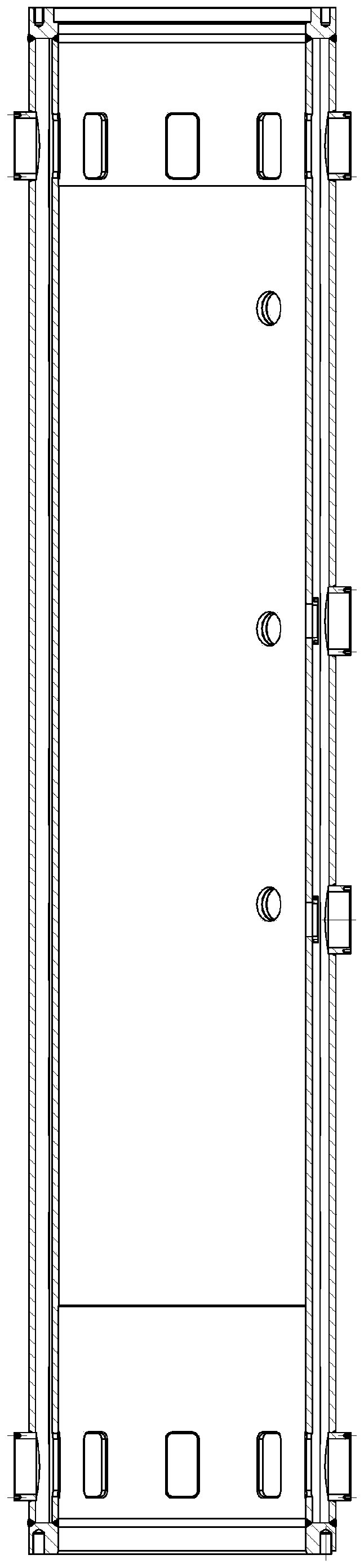
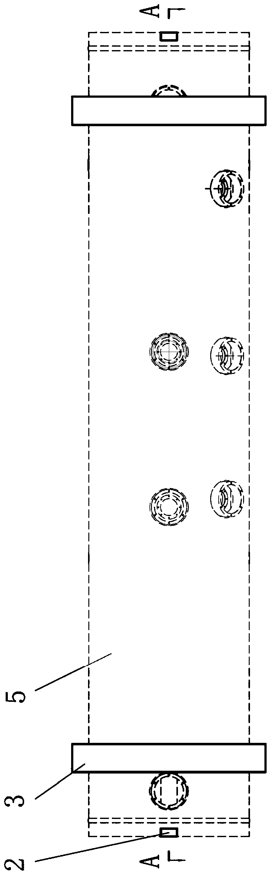
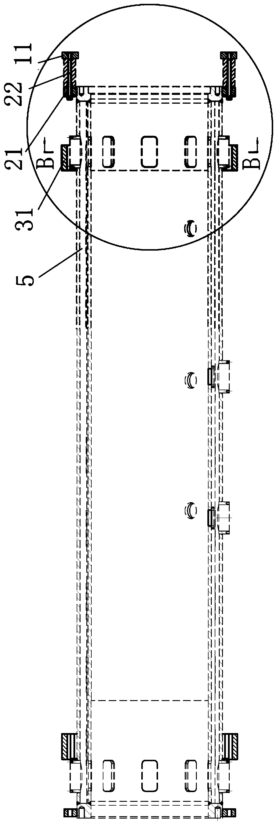
[0060] In order to enable large thin-walled double-layer cylinder parts to be clamped and positioned on a heavy-duty lathe, so that the inner hole can be processed without large deformation when th...


PUM


Abstract

The invention discloses a large thin-wall double-layer cylinder deep hole machining device and a machining method thereof. The device comprises a lathe, a fixing mechanism, a supporting mechanism anda guiding floating boring head, wherein the fixing mechanism is mounted on the end portion of a cylinder body, located on the outer side of a flange, and is used for fixing the cylinder body to a lathe flower disc of the lathe; the supporting mechanism comprises a supporting ring, the supporting ring fixedly sleeves the outer side of the cylinder body and is used for supporting the cylinder body by carrier rollers, and the guiding floating boring head is detachably mounted on a lathe boring rod of the lathe and is used for machining an inner hole of the cylinder body. According to the large-scale thin-wall double-layer cylinder deep hole machining device and the machining method thereof, the cylinder body is fixedly clamped on the lathe flower disc through the fixing mechanism, and the cylinder body deformation caused by clamping can be reduced; the cylinder body is supported by the carrier rollers of the supporting mechanism, the rigidity of a shell on the outer side of the cylinder body can be increased, and the cylinder body deformation caused by the supporting of the carrier rollers can be reduced; and meanwhile, the inner hole of the cylinder body can be machined through the guide floating boring head, so that the size precision, the shape bit precision and the surface roughness requirement of the inner hole machining can be guaranteed.

Description

technical field [0001] The invention relates to the technical field of thin-walled cylinder processing, in particular to a large-scale thin-walled double-layered cylinder deep hole processing device and a processing method thereof. Background technique [0002] Deep hole processing of thin-walled parts has always been a difficult point in lathe processing, especially for deep hole processing of large thin-walled cylindrical workpieces, such as deep hole processing for the upper hammer barrel of large hydraulic piling hammers; currently hydraulic piling hammers are working , the hammer core needs to reciprocate up and down in the inner hole of the upper hammer barrel. In order to ensure the normal use and safety of the hydraulic piling hammer, when processing the upper hammer barrel, the dimensional accuracy and straight line of the upper hammer barrel must be checked. There are high requirements for high precision, and the inner hole is required to have a low surface roughne...

Claims


Application Information

Patent Timeline
IPC IPC(8): B23B41/02B23B43/00
CPCB23B41/02B23B43/00
Inventor 贾超解文科解虎驹郑田张维敏李文进翟江涛许海健
Owner TAIZHONG TIANJIN BINHAI HEAVY MACHINERY
Why Eureka
Try Eureka