
Polishing device of stainless steel pipe

A technology of polishing device and stainless steel tube, which is applied in the direction of grinding/polishing safety device, grinding/polishing equipment, surface polishing machine tool, etc. It can solve the problems of reducing the polishing efficiency of the equipment, easy to drop the flip cover suddenly, and inconvenient transportation of the equipment, etc. Achieve the effect of simple structure, preventing sudden drop and ensuring stability

Inactive Publication Date: 2018-12-18
德阳市旌龙再生资源有限公司
View PDF0 Cites 4 Cited by
  • Summary
  • Abstract
  • Description
  • Claims
  • Application Information

AI Technical Summary

Problems solved by technology

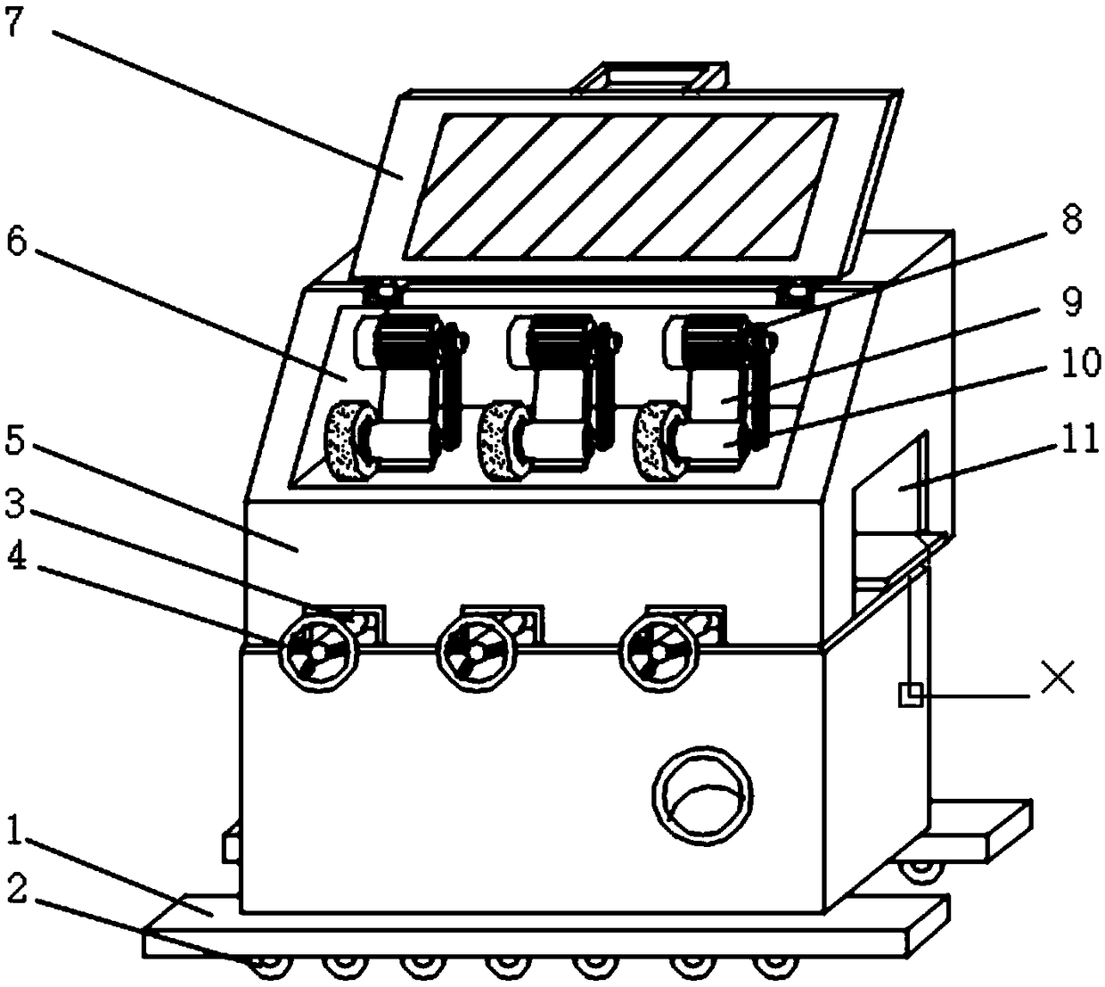
[0002] The polishing device refers to a device that uses mechanical, chemical or electrochemical effects to reduce the surface roughness of the workpiece to obtain a bright and flat surface; the existing polishing device has certain disadvantages in the process of use, no mobile base design, which brings inconvenience to the handling of the equipment, and there is no directional shaft design, the flip cover is easy to fall suddenly, and when the workpiece enters the equipment for polishing, if it is not placed accurately on the processing channel, it is easy to shift, resulting in invalid polishing and reducing The polishing efficiency of the equipment has a certain impact on the use of the polishing device. Therefore, we propose a stainless steel tube polishing device

Method used


Image

  • Polishing device of stainless steel pipe
  • Polishing device of stainless steel pipe
  • Polishing device of stainless steel pipe

Examples


Embodiment Construction

[0022] In order to make the purpose, technical solution and advantages of the present invention clearer, the technical solution of the present invention will be described in detail below. Apparently, the described embodiments are only some of the embodiments of the present invention, but not all of them. Based on the embodiments of the present invention, all other implementations obtained by persons of ordinary skill in the art without making creative efforts fall within the protection scope of the present invention.

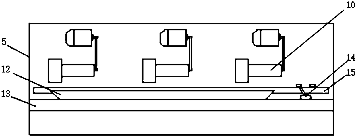
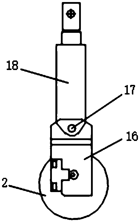
[0023] see Figure 1-Figure 4 As shown, the invention provides a stainless steel tube polishing device, comprising:

[0024] Polishing mechanism, described polishing mechanism comprises housing 5 and inner cavity 6, and the lower end surface of described housing 5 is all provided with mobile base 1 near the position of both sides, and the lower end surface groove of mobile base 1 is parallel A plurality of rollers 2 are installed equidistantly. The outer surfa...


PUM


Abstract

The invention discloses a polishing device of a stainless steel pipe. The device comprises a polishing and grinding mechanism, the polishing and grinding mechanism comprises a shell body and an innercavity, wherein movable bases are arranged at the position, close to the two sides, of the lower end face of the shell body respectively, and a plurality of rolling wheels are movably installed in thegrooves in the lower end faces of the movable bases in parallel at equal intervals, protective shells are arranged on the outer surfaces of the rolling wheels, and hydraulic telescopic rods are arranged at the upper ends of the protective shells; and turning joints are arranged at the joints of the hydraulic telescopic rods and the protective shells, three adjusting hand wheels are transversely arranged on the front end face of the shell body at equal intervals, and a feeding hole is formed in one side of the shell body. In conclusion, the polishing device of the stainless steel pipe has thebeneficial effects that the movable bases, orienteering rotating shafts and guide bases are adopted, the stability of equipment during working can be further ensured while convenience is brought to carrying of the equipment, a turnover cover can be prevented from falling down suddenly, the polishing efficiency of the equipment is improved, the structure is simple, and the use is convenient.

Description

technical field [0001] The invention relates to the field of polishing devices, in particular to a stainless steel tube polishing device. Background technique [0002] The polishing device refers to a device that uses mechanical, chemical or electrochemical effects to reduce the surface roughness of the workpiece to obtain a bright and flat surface; the existing polishing device has certain disadvantages in the process of use, no mobile base design, which brings inconvenience to the handling of the equipment, and there is no directional shaft design, the flip cover is easy to fall suddenly, and when the workpiece enters the equipment for polishing, if it is not placed accurately on the processing channel, it is easy to shift, resulting in invalid polishing and reducing The polishing efficiency of the equipment has a certain impact on the use of the polishing device. Therefore, we propose a stainless steel tube polishing device. Contents of the invention [0003] The purpo...

Claims


Application Information

Patent Timeline
Patent Type & Authority Applications(China)
IPC IPC(8): B24B29/08B24B27/00B24B41/02B24B55/00B24B41/00
CPCB24B29/08B24B27/0007B24B27/0069B24B27/0076B24B41/005B24B41/02B24B55/00
Inventor 郑尚华
Owner 德阳市旌龙再生资源有限公司
Learn More