
A working method of an H-beam welding bead polishing and derusting device

A working method, the technology of H-shaped steel, which is applied in the direction of surface polishing machine tools, grinding drive devices, grinding/polishing equipment, etc., can solve the problems of grinding operation influence, easy to produce offset, and inability to adapt to workpieces of different sizes, etc. To achieve the effect of reducing labor intensity

Inactive Publication Date: 2020-06-02
广东德源钢结构工程有限公司
View PDF6 Cites 0 Cited by
  • Summary
  • Abstract
  • Description
  • Claims
  • Application Information

AI Technical Summary

Problems solved by technology

[0004] Although this patent can improve work efficiency, it still requires workers to manually turn over the workpiece, which brings additional labor intensity to the workers; this patent lacks a device for limiting the workpiece, which makes it easier for the workpiece to be polished during the grinding process. Offset occurs, which affects the subsequent grinding operation of the workpiece; the cleaning head in this patent is not adjustable, so that the cleaning head can only grind the weld bead of a workpiece with a certain width, and cannot adapt to different sizes The workpieces cannot meet the needs of the market

Method used


Image

  • A working method of an H-beam welding bead polishing and derusting device
  • A working method of an H-beam welding bead polishing and derusting device
  • A working method of an H-beam welding bead polishing and derusting device

Examples


Embodiment Construction

[0035] The following will be combined with Figure 1 to Figure 10 The present invention is described in detail, and the technical solutions in the embodiments of the present invention are clearly and completely described. Apparently, the described embodiments are only some of the embodiments of the present invention, not all of them. Based on the embodiments of the present invention, all other embodiments obtained by persons of ordinary skill in the art without making creative efforts belong to the protection scope of the present invention.

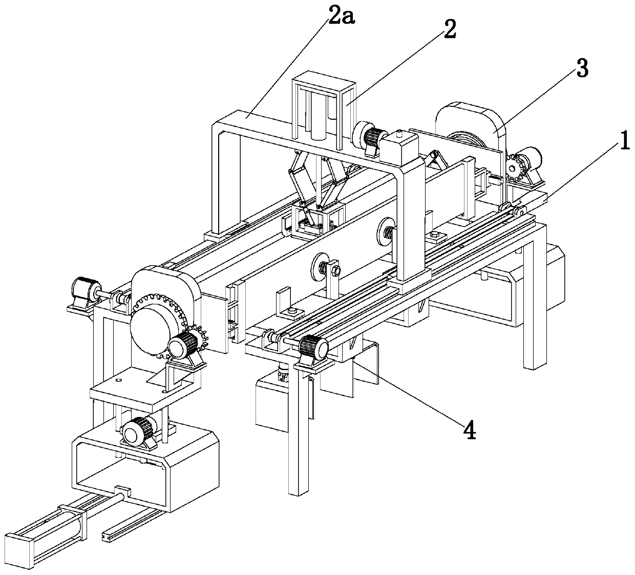
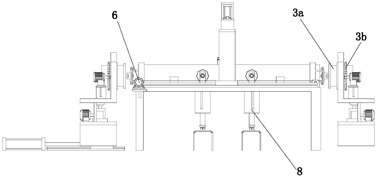
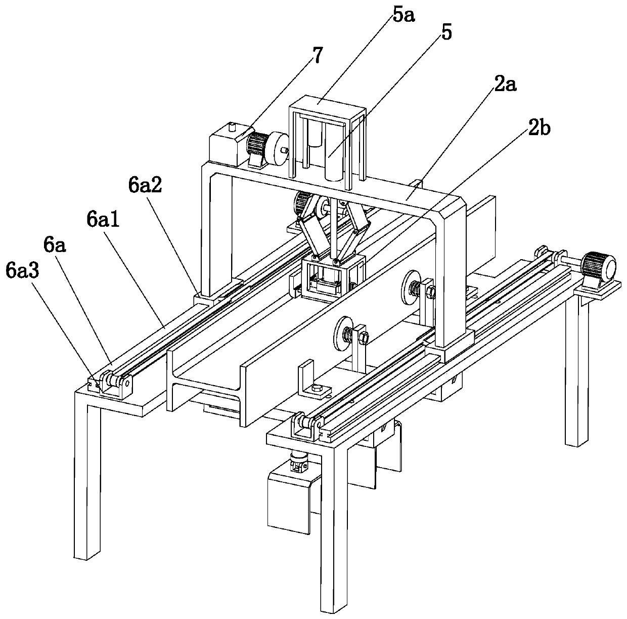
[0036] The present invention provides a kind of H-beam weld bead polishing derusting device here by improving, as Figure 1-Figure 10 As shown, it includes a workbench 1, a polishing and derusting mechanism 2, an overturning mechanism 3 and a limit mechanism 4. Below, the overturning mechanism 3 is arranged on both sides of the workbench 1, and the overturning mechanism 3 includes two symmetrically arranged overturning assemblies 3a, and...


PUM


Abstract

The invention relates to the field of steel component machining equipment, in particular to a working method of an H-shaped steel welding bead polishing derusting device. The derusting device comprises a workbench, a polishing derusting mechanism, a turning mechanism and a limiting mechanism. The turning mechanism comprises two turning assemblies which are arranged symmetrically. The polishing derusting mechanism comprises a portal frame, a derusting assembly, a lifting assembly and a moving assembly. The derusting assembly comprises a mounting frame, a scrap suction component and a welding bead derusting component arranged at the bottom of the mounting frame. A derusting brush used for derusting workpieces is arranged at the bottom of the mounting frame. The working method of the H-shapedsteel welding bead polishing derusting device has the beneficial effects that the workpieces can be automatically turned through the turning mechanism, and the welding bead derusting component can derust welding beads of workpieces with different sizes through a derusting plate on a sliding plate; and the workpieces can be automatically limited through the limiting mechanism, so that the workpieces are not prone to deviation in the polishing process.

Description

technical field [0001] The invention relates to the field of steel component processing equipment, in particular to a working method of an H-shaped steel weld bead polishing and derusting device. Background technique [0002] In fields where H-shaped steel is used more, such as steel structure engineering, etc., the weld quality requirements for the welding of H-shaped steel webs and flange plates in steel structural members are getting higher and higher. The traditional cleaning of the flange mainly uses sandblasting. Rust removal and hand-held grinder rust removal, the two methods of rust removal have many disadvantages, the main disadvantage of the former is high power consumption and waste of resources, the main disadvantage of the latter is high labor intensity, serious pollution, and certain damage to human health. Impact. [0003] The invention patent with the patent number CN107097116A relates to an H-shaped steel wing plate welding bead grinding and derusting devic...

Claims


Application Information

Patent Timeline
Patent Type & Authority Patents(China)
IPC IPC(8): B24B27/033B24B29/02B24B41/02B24B47/04B24B41/06B24B47/22B24B47/12
CPCB24B27/033B24B29/005B24B29/02B24B41/02B24B41/06B24B47/04B24B47/12B24B47/22
Inventor 董英山郭弘王国庆
Owner 广东德源钢结构工程有限公司
Learn More