Wide-size particle field measuring method based on IPI focused image and defocused image

A measurement method and particle field technology, applied in measurement devices, particle size analysis, particle and sedimentation analysis, etc., can solve the problems of reducing the imaging field of view, limiting the lower limit of particle size measurement, limiting the upper limit of particle size measurement, etc. Large, high precision, wide measuring range effect

Inactive Publication Date: 2018-12-14
TIANJIN UNIV
View PDF5 Cites 0 Cited by
  • Summary
  • Abstract
  • Description
  • Claims
  • Application Information

AI Technical Summary

Problems solved by technology

When the particle fringe spacing is smaller than the resolution of the recording medium, that is, when the sampling law is not satisfied, the fringe pattern of the particle cannot be recorded, thus limiting the upper limit of particle size measurement
For the focused image, the distance between the two point images is proportional to the particle size. When the particle size is small, especially for small particles, the two point images may overlap, and the two point images may not be observed. By zooming in, it is possible to observe Two-point image, but zooming in will reduce the imaging field of view, so the IPI focused image method limits the lower limit of particle size measurement
[0005] Therefore, due to the limitation of the resolution of the recording medium, the IPI defocused image will limit the maximum measurable particle size, and the focused image will limit the minimum measurable particle size. For wide-sized particle fields, this conventional The IPI focus image or defocus image method will no longer apply

Method used


Image

  • Wide-size particle field measuring method based on IPI focused image and defocused image
  • Wide-size particle field measuring method based on IPI focused image and defocused image
  • Wide-size particle field measuring method based on IPI focused image and defocused image

Examples


Embodiment Construction

[0027] In order to make the purpose, technical solution and advantages of the present invention clearer, the implementation manners of the present invention will be further described in detail below.

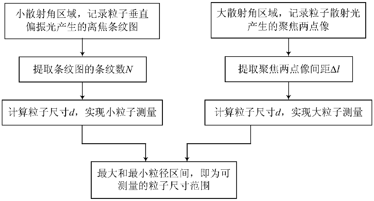
[0028] A wide-scale particle field measurement method based on IPI focused image and defocused image, see Figure 1-Figure 4 , the measurement method includes the following steps:

[0029] 1. Build the optical system

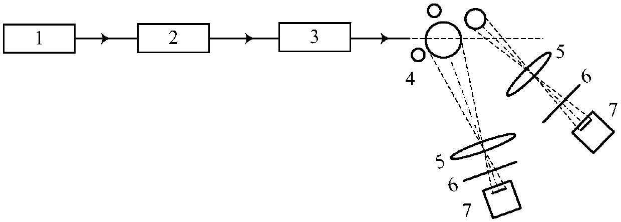
[0030] according to figure 2 Build an optical path system, including: laser 1, beam expander collimation system 2, beam compression system 3, particle field 4, imaging lens 5, polarizer 6, and CCD 7.

[0031] Laser 1 is a semiconductor laser with wavelength λ=532 nm. The thin beam emitted by the laser 1 is expanded, filtered, and collimated by the beam expander and collimator system 2, and then compressed into a sheet-like beam by the beam compression system 3 composed of two cylindrical lenses. The width of the sheet-like beam is 1.2mm .

[0032] The imagin...


PUM

PropertyMeasurementUnit
wavelengthaaaaaaaaaa
diameteraaaaaaaaaa
refractive indexaaaaaaaaaa

Abstract

The invention discloses a wide-size particle field measuring method based on IPI focused image and defocused image. According to the method, by adopting a double-path IPI system, in a small scatteringangle region, a defocused fringe pattern of vertical polarized light of particles is recorded; in a large scattering angle region, focused two-point images of scattered light of the particles are recorded; the fringe number N of the collected fringe pattern and the distance delta l between the focused two-point images are extracted; calculation is performed to obtain particle sizes; and the minimum and maximum particle size values measurable for the double-path system are namely a measurable particle size range. The measuring method combining the IPI focused image and defocused image has thecharacteristics of being simple in principle, high in measuring precision, high in practicability and the like, and can be used for measurement of wide-size particle fields such as a spray particle field, an aerosol particle field and the like.

Description

technical field [0001] The invention relates to the technical field of particle field measurement, in particular to a wide-size particle field measurement method based on an IPI focused image and a defocused image. Background technique [0002] Particles refer to tiny solids, bubbles and liquid droplets with sizes below millimeters to microns and nanometers, and are widely used in industrial production and scientific research. Particle size measurement is a long-term research direction in this field, which is of great significance. At present, a variety of particle size measurement methods based on optical principles have been proposed, and each method has a certain measurement range due to the limitations of the principle and system. [0003] Interferometric particle imaging (IPI) is a particle measurement method that has attracted much attention at present. Its basic principle is based on the Mie scattering theory, by measuring the fringe number / fringe frequency of the pa...

Claims


Application Information

Patent Timeline
Patent Type & Authority Applications(China)
IPC IPC(8): G01N15/02
CPCG01N15/0227
Inventor 吕且妮徐捷尉小雪
Owner TIANJIN UNIV
Why Eureka
Try Eureka