
An Optimum Design Method for Magnetic Circuit Structure of Electromagnetic Flow Sensor

A technology of electromagnetic flow and optimized design, applied in the application of electromagnetic flowmeter to detect fluid flow, volume/mass flow generated by electromagnetic effect, measure flow/mass flow, etc. It can improve the accuracy and efficiency, expand the lower limit of instrument measurement, and improve the effect of the induced electromotive force signal.

Active Publication Date: 2022-05-20
HEFEI UNIV OF TECH
View PDF25 Cites 0 Cited by
  • Summary
  • Abstract
  • Description
  • Claims
  • Application Information

AI Technical Summary

Problems solved by technology

Since there are many influencing factors, and different combinations of various factors will form different magnetic circuits, it will take a lot of time to use the traversal simulation test method, and it is impossible to reveal the essential characteristics of each parameter of the magnetic circuit structure

Method used


Image

  • An Optimum Design Method for Magnetic Circuit Structure of Electromagnetic Flow Sensor
  • An Optimum Design Method for Magnetic Circuit Structure of Electromagnetic Flow Sensor
  • An Optimum Design Method for Magnetic Circuit Structure of Electromagnetic Flow Sensor

Examples


Embodiment Construction

[0036] In order to make the purpose, technical solution and advantages of the present invention clearer, the method for optimizing the design of the magnetic circuit structure of an electromagnetic flow sensor proposed by the present invention will be further explained and described below in conjunction with the accompanying drawings.

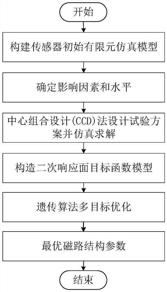
[0037] The present invention takes the optimized design of the magnetic circuit of the DN65 round tube electromagnetic flow sensor as an example, figure 1 Is the flow chart that the present invention implements, and concrete steps are as follows:

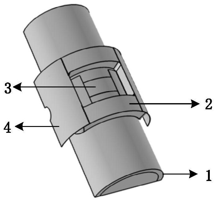
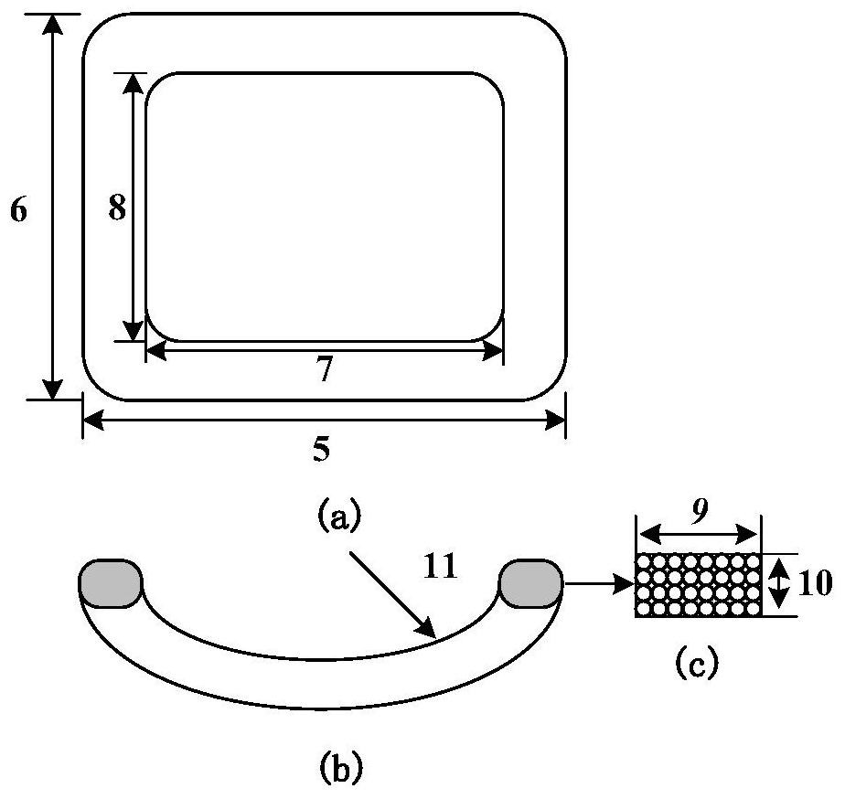
[0038] Step (1) According to the structural parameters and material properties of the unoptimized electromagnetic flow sensor solid prototype, construct a three-dimensional geometric model in an axisymmetric manner (such as figure 2 As shown), and based on the three-dimensional geometric model, a coupled simulation model of the flow field, magnetic field and electric field is established, and the in...


PUM


Abstract

The invention relates to a magnetic circuit structure optimization design method of an electromagnetic flow sensor. It includes the following steps: constructing the initial finite element simulation model of the sensor according to the physical prototype of the sensor; designing the level table of influencing factors, designing the test program by using the central composite design (CCD) method and simulating and solving the test program; inputting the design variables and correspondingly solving the response Value output, constructing the response surface objective function of each response required for optimization; using genetic algorithm to nonlinear multi-objective optimization of the response surface objective function to obtain the optimal magnetic circuit structure parameters; three-dimensional modeling based on the optimal magnetic circuit structure parameters And finite element simulation solution to verify the optimization effect. The present invention can carry out the comprehensive optimization design of the magnetic circuit structure of the sensor under the limitation of constant power consumption of the system and certain dynamic characteristics, thereby improving the measurement accuracy of the sensor, improving the efficiency of research and development, reducing the production cost, and being beneficial to realize the normal structure of the magnetic circuit structure of the sensor. towards development.

Description

technical field [0001] The invention relates to the technical field of flow sensor structure design, in particular to a magnetic circuit structure optimization design method of an electromagnetic flow sensor. Background technique [0002] Electromagnetic flow sensors have the advantages of simple structure, no pressure loss, high precision, large measurement range, and reliable use, and are widely used in flow measurement fields such as industry, agriculture, and medicine. In order to achieve high-precision measurement of electromagnetic flow sensors, it is necessary to enhance the magnetic induction intensity and improve the uniformity of the magnetic field, so that the induced electromotive force signals at both ends of the electrodes are enhanced. There are generally three ways to increase the magnetic induction intensity, one is to increase the excitation current, the other is to increase the number of coil turns, and the third is to increase the amount of ferromagnetic ...

Claims


Application Information

Patent Timeline
Patent Type & Authority Patents(China)
IPC IPC(8): G01F1/58
CPCG01F1/586Y02T90/00
Inventor 梁利平齐飞燕葛玉石秦晓文柴玲宾王鸣黄云志杨双龙徐科军魏坤
Owner HEFEI UNIV OF TECH
Learn More