
A surface coating device based on pvd technology

A surface coating and technology technology, which is applied in the field of surface coating devices based on PVD technology, can solve problems that affect the sputtering quality of workpieces to be plated, cannot complete the clamping of different types of parts, and have uneven coatings on the surface of workpieces to be plated. Close contact, guaranteed reliability and high efficiency

Active Publication Date: 2020-08-14
深圳市锦瑞新材料股份有限公司
View PDF5 Cites 0 Cited by
  • Summary
  • Abstract
  • Description
  • Claims
  • Application Information

AI Technical Summary

Problems solved by technology

[0004] This technical solution can realize the placement of more workpieces to be plated and improve the coating efficiency, but the rod in the device can only be rotated around the central axis, resulting in that one side of the workpiece to be plated cannot accept the attachment of ions, which in turn leads to The coating on the surface of the workpiece is uneven, which ultimately affects the sputtering quality of the workpiece to be plated; the device cannot complete the clamping of different types of parts

Method used


Image

  • A surface coating device based on pvd technology
  • A surface coating device based on pvd technology
  • A surface coating device based on pvd technology

Examples


Embodiment Construction

[0024] In order to make the technical means, creative features, goals and effects achieved by the present invention easy to understand, the present invention will be further described below in conjunction with specific embodiments.

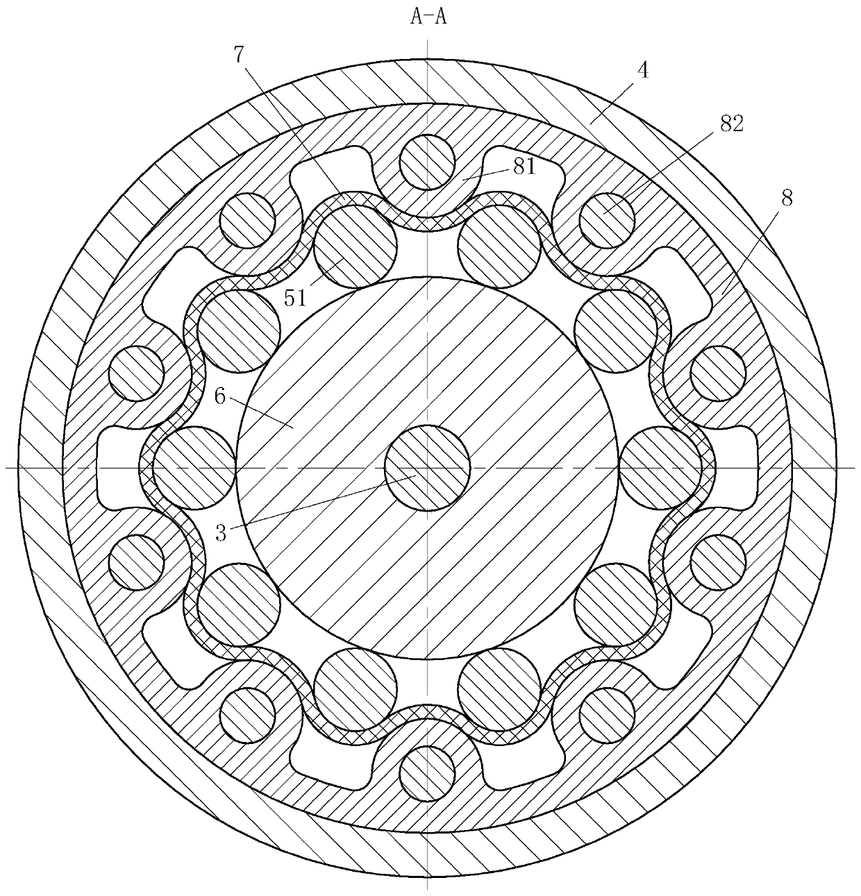
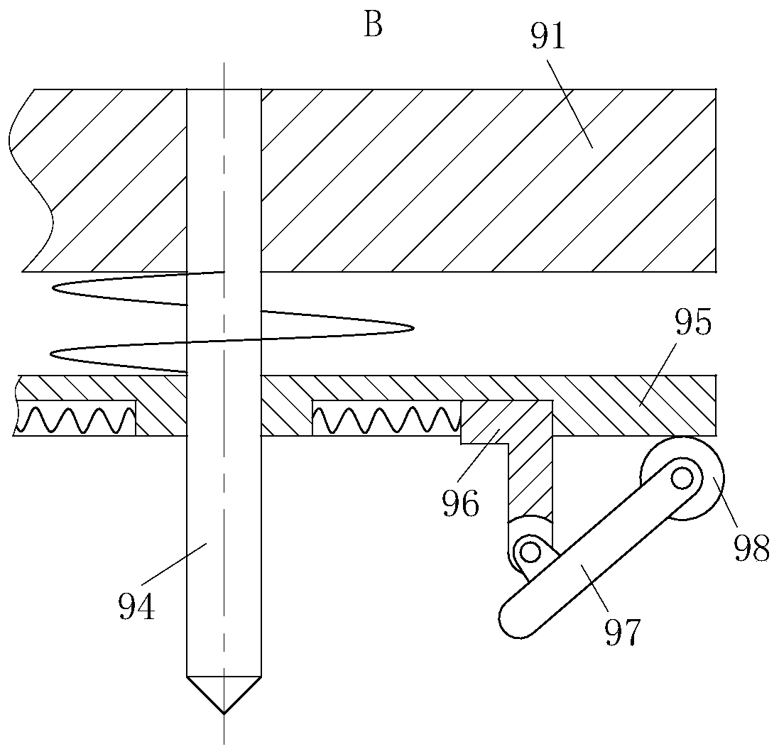
[0025] Such as Figure 1 to Figure 4 As shown, a surface coating device based on PVD technology of the present invention includes a housing 1, a target 2, and a motor. The housing 1 is hollow cylindrical, and the inner wall of the housing 1 is provided with a target 2 , the bottom of the housing 1 is provided with a motor; it also includes a connecting shaft 3, a lower support plate 4, a thimble 5, a friction wheel 6, a friction belt 7, an extrusion ring 8, a driven support module 9, and the end of the motor shaft It is fixedly connected with the lower end of the connecting shaft 3; the upper end of the connecting shaft 3 is fixedly connected with the friction wheel 6; the upper side of the friction wheel 6 is provided with a lower support disc 4;...


PUM


Abstract

The invention belongs to the technical field of film coating, and particularly relates to a surface film coating device based on a PVD technology. The surface film coating device comprises a shell, target materials, a motor, a connecting shaft, a lower supporting disc, ejector pins, a friction wheel, friction belts, an extrusion ring and a driven supporting module, wherein the friction wheel is fixedly connected to the upper end of the connecting shaft; a cylindrical groove in the lower supporting disc is internally and fixedly connected to the outer side surface of the extrusion ring; and a group of hemispherical protrusions are uniformly arranged on the inner side of the extrusion ring. According to the surface film coating device, surfaces of discs at the lower ends of the ejector pinsare in contact with a cylindrical surface of the friction wheel, the hemispherical protrusions on the extrusion ring and the discs at the lower ends of the ejector pins are arranged in a staggered mode, the friction belts are arranged between the extrusion ring and the discs at the lower ends of the ejector pins, the driven supporting module is arranged at the upper end of the shell, and thereforea to-be-coated workpiece on the lower supporting disc can rotate around the connecting shaft and auto-rotate around the ejector pins, so that the surface of the to-be-coated workpiece uniformly receives ions impacting from the target materials, and then the surface of a shaft part is uniformly sputtered.

Description

technical field [0001] The invention belongs to the technical field of coating, in particular to a surface coating device based on PVD technology. Background technique [0002] Sputtering is a physical vapor deposition technology. The principle of sputtering is to use high-energy plasma generated by glow discharge or ion beam to hit the target material in a vacuum environment, and bombard the atoms in the target material from the target material by means of momentum transfer. out and deposited on the substrate to form a thin film. Because sputtering can achieve better deposition efficiency, precise composition control, and lower manufacturing costs, it has been widely used in the production of various metal and non-metal films in industry. [0003] There are also some technical solutions of sputtering devices in the prior art. For example, a Chinese patent with application number 2010106052656 discloses a sputtering device, which includes a body, a carrying device and at le...

Claims


Application Information

Patent Timeline
Patent Type & Authority Patents(China)
IPC IPC(8): C23C14/34C23C14/50
CPCC23C14/34C23C14/505
Inventor 王志伟
Owner 深圳市锦瑞新材料股份有限公司
Learn More