
A multi-stage electric heating tube and a manufacturing method thereof

An electric heating tube and heating wire technology, applied in ohmic resistance heating parts, heating element materials, heating element shapes, etc., can solve the problems of inability to adjust, low temperature control accuracy, accelerated product aging, etc., to improve safety and Reliability, improve temperature control accuracy, improve heating efficiency

Pending Publication Date: 2018-12-11
宁波市扬天磁能科技有限公司
View PDF3 Cites 2 Cited by
  • Summary
  • Abstract
  • Description
  • Claims
  • Application Information

AI Technical Summary

Problems solved by technology

The commonly used heating tube is single-stage control. The power of the heating tube is changed by changing the voltage through the silicon controlled silicon on the circuit board. The temperature control speed of the single-stage heating tube is slow, and a large amount of water flow is required for cooling after heating. The heat sink needs to be installed on the thyristor. The heat sink is large in size and high in heat, which will accelerate the aging of the product. The machine that controls the heating tube through the thyristor cannot effectively prevent electromagnetic interference. When the product encounters interference Prone to control chip disorder
The heating layer of another multi-stage heating tube is formed by a heating wire from the beginning to the end at one time, and the conductive fixing ring is used to fix the heating wire in the middle of the heating tube. Appropriate power to adjust the value to match the machine temperature, the heating effect is limited

Method used


Image

  • A multi-stage electric heating tube and a manufacturing method thereof
  • A multi-stage electric heating tube and a manufacturing method thereof

Examples


Embodiment 1

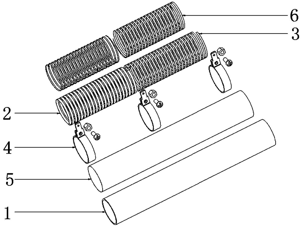
[0034] Such as figure 1 with figure 2 As shown, a multi-stage electric heating tube is used for heating liquid in drinking water equipment. The multi-stage electric heating tube includes a diversion tube 1 and a heating layer wrapped outside the diversion tube 1. The diversion tube 1 is made of stainless steel. The flow direction of the liquid in the draft tube 1 is downward inflow and upward exit, and the heating layer is energized and heated to increase the temperature of the liquid in the draft tube 1 . A first insulating layer 5 is arranged between the flow guide tube 1 and the heating layer, and the first insulating layer 5 is made of an insulating film to isolate the flow guide tube 1 from the heating layer to prevent leakage.

[0035] In this embodiment, the heating layer is composed of two sections of heating elements. The two sections of heating elements are respectively made of the first heating wire 2 and the second heating wire 3. The first heating wire 2 and the...

Embodiment 2

[0037] In this embodiment, on the basis of the above embodiments, the first heating wire 2 and the second heating wire 3 are made of the same material, and the thickness, width and length of the two are different, and different power sections can be configured according to different requirements. , to expand the heating range of the heating tube, suitable for heating requirements of different environments and different liquids.

Embodiment 3

[0039] This embodiment is different from the above embodiments in that the materials of the first heating wire 2 and the second heating wire 3 are also different, which can further expand the heating range of the heating tube and improve the heating accuracy.


PUM


Abstract

The invention discloses a multi-stage electric heating tube, comprising a flow guiding tube and a heating layer, wherein the heating layer wraps the flow guiding tube, the heating layer is composed oftwo sections of heating elements, two ends of the heating elements are fixed by conductive coils, and a manufacturing method of the multi-stage electric heating tube is also disclosed. The multi-stage electric heating tube can be configured with different power segments according to the heating demand to realize the segmented control of a heating tube, and different power can be selected for heating according to different temperatures, so as to improve the heating efficiency.

Description

technical field [0001] The invention relates to the field of heating elements, in particular to a multi-stage electric heating tube and a manufacturing method thereof. Background technique [0002] The heating tube is a commonly used liquid heating element, which has the advantage of high heating efficiency. The heating tube is heated by the heating layer wrapped around it. The commonly used heating tube is single-stage control. The power of the heating tube is changed by changing the voltage through the silicon controlled silicon on the circuit board. The temperature control speed of the single-stage heating tube is slow, and a large amount of water flow is required for cooling after heating. The heat sink needs to be installed on the thyristor. The heat sink is large in size and high in heat, which will accelerate the aging of the product. The machine that controls the heating tube through the thyristor cannot effectively prevent electromagnetic interference. When the prod...

Claims


Application Information

Patent Timeline
Patent Type & Authority Applications(China)
IPC IPC(8): H05B3/40H05B3/02H05B3/10
CPCH05B3/02H05B3/10H05B3/40
Inventor 王建定
Owner 宁波市扬天磁能科技有限公司
Learn More