Microwave photonic radar detection method and device based on multiple optical reference signals

A reference signal and microwave photon technology, applied in the field of microwave photon radar detection, can solve the problems of reducing signal bandwidth, increasing system cost, and exacerbating envelope dislocation, etc., to achieve the effect of increasing effective bandwidth, expanding detection range, and high distance resolution

Active Publication Date: 2019-10-29
NANJING UNIV OF AERONAUTICS & ASTRONAUTICS
View PDF5 Cites 0 Cited by
  • Summary
  • Abstract
  • Description
  • Claims
  • Application Information

AI Technical Summary

Problems solved by technology

In order to expand the detection range, the system needs to use a photodetector with a larger bandwidth and a digital receiving module with a higher rate, which will significantly increase the cost of the system, and may need to improve the receiving sensitivity and the number of bits of signal analog-to-digital conversion. trade-offs on indicators
On the other hand, a larger detection range will increase the relative delay between the echo and a single reference signal, exacerbating the envelope misalignment between the two signals
This will narrow the effective signal bandwidth, leading to a deterioration of the radar range resolution

Method used


Image

  • Microwave photonic radar detection method and device based on multiple optical reference signals
  • Microwave photonic radar detection method and device based on multiple optical reference signals
  • Microwave photonic radar detection method and device based on multiple optical reference signals

Examples


Embodiment Construction
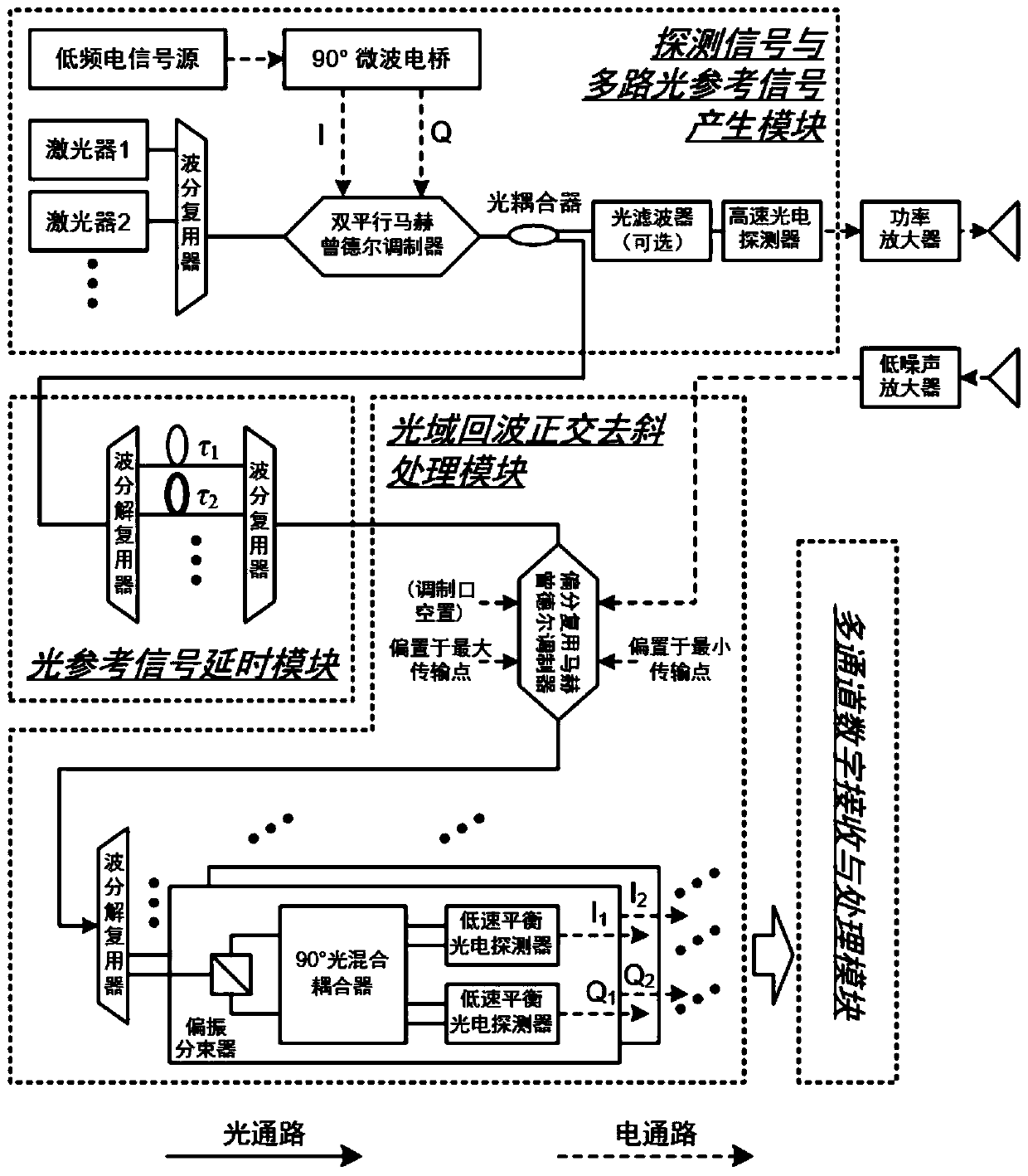
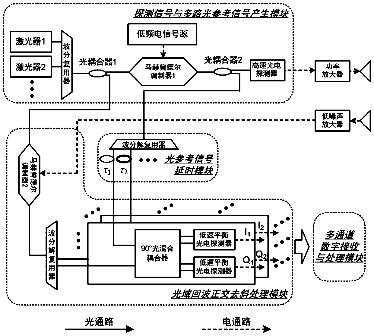
[0034] The inventive idea of ​​the present invention is to improve the existing de-skew receiving microwave photonic radar, use the parallel processing freedom of the optical domain to generate multiple reference signals, and effectively connect multiple low-speed digital receiving modules in parallel to achieve low cost , Broadband microwave detection with high performance and large detection range.

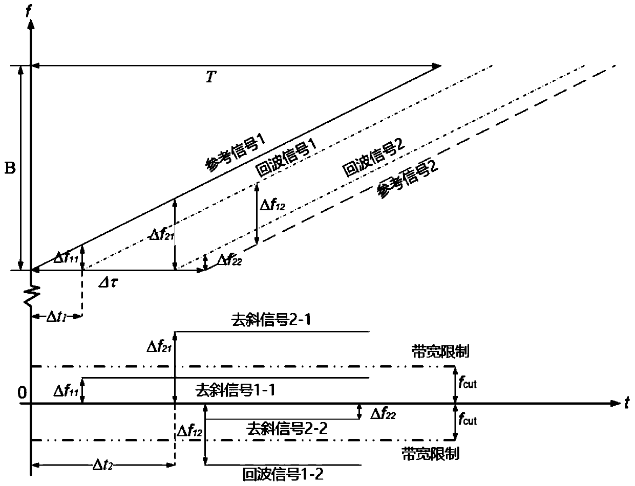
[0035] Specifically, the microwave photonic radar detection method based on multiple optical reference signals modulates the low-frequency electrical signal into an optical carrier group composed of multiple optical carriers with different wavelengths to generate multiple optical carrier electrical signals. Modulate the optical signal, divide the modulated optical signal into two channels, and use one of them to generate a broadband radio frequency detection signal; after assigning a different delay to each optical carrier electrical signal in the other modulated optical signal, Th...


PUM


Abstract

The invention discloses a microwave photon radar detection method based on multiple optical reference signals, comprising modulating a low-frequency electric signal on a beam of optical carriers composed of optical carriers with different wavelengths to generate a modulated optical signal including a plurality of optical electric signals, dividing the modulated optical signal into two paths to generate a broadband radio frequency detection signal on one of the paths; after giving different time delays to each optical signal of the other modulated optical signal, performing optical domain orthogonal de-skew processing on the radar echo with each optical signal as optical reference signal to obtain multiple groups of in-phase and orthogonal low frequency de-skew signals; fusing the low-frequency de-sloping signals to complete the splicing of the detection ranges corresponding to the de-sloping signals of each group. The invention also discloses a microwave photon radar detection device based on multiple optical reference signals. The invention can utilize a low-cost low-speed photoelectric conversion and digital receiving module to realize the large-scale expansion of the detection range of the microwave photon radar.

Description

Technical field [0001] The invention relates to a microwave photon radar detection method, in particular to a microwave photon radar detection method and device based on multiple optical reference signals. Background technique [0002] Microwave photonic radar is a new system of microwave radar. It transfers the broadband waveform generation, signal frequency multiplication, up-down conversion, amplitude and phase delay control and other functions in the classic radar radio frequency front-end to the optical domain through electro-optic and optoelectronic conversion, which can enable the photonic technology to carry large bandwidth, low transmission loss, and resistance. Many advantages such as electromagnetic interference are integrated into the radar radio frequency front end. Because it can break through the development bottleneck of the existing electronic radio frequency front-end, microwave photon radar is an important technical way to realize the instantaneous bandwidth e...

Claims


Application Information

Patent Timeline
Patent Type & Authority Patents(China)
IPC IPC(8): H04B10/69G01S13/02G01S13/10G01S17/88
CPCG01S13/0209G01S13/106G01S17/88H04B10/691
Inventor 潘时龙叶星炜张方正杨悦
Owner NANJING UNIV OF AERONAUTICS & ASTRONAUTICS
Why Eureka
Try Eureka