
A method and a system for modeling equivalent satellite attitude motion of vertical rods in the deployment process of a loop antenna

A technology of satellite attitude and modeling method, applied in special data processing applications, instruments, electrical digital data processing, etc., to achieve the effect of improving rapidity, ensuring calculation accuracy, and reducing modeling complexity

Active Publication Date: 2018-12-11
BEIJING INST OF CONTROL ENG
View PDF0 Cites 4 Cited by
  • Summary
  • Abstract
  • Description
  • Claims
  • Application Information

AI Technical Summary

Problems solved by technology

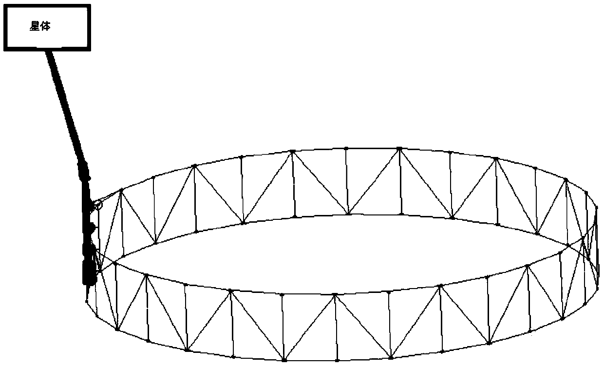
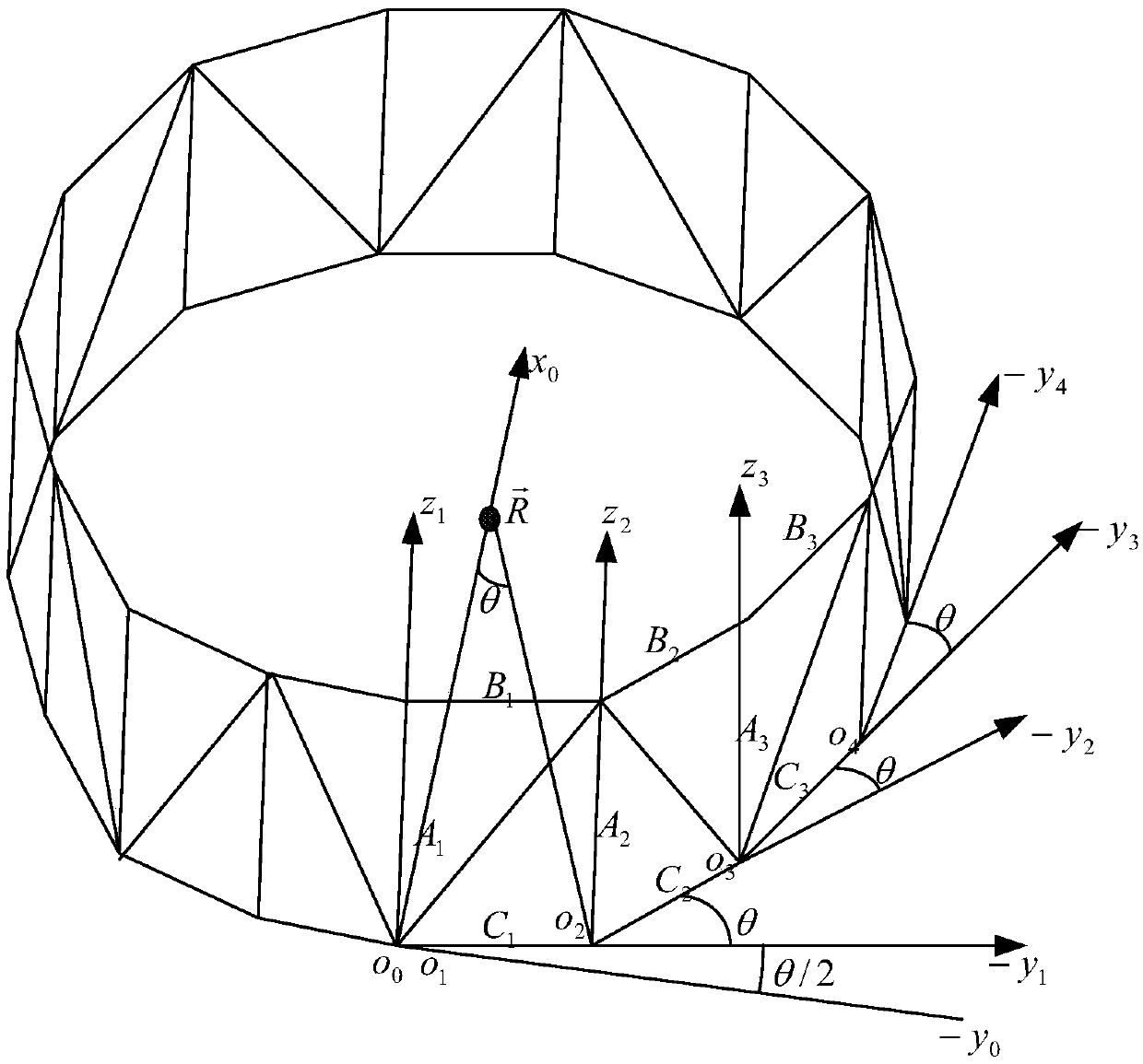
[0003] The technical problem solved by the present invention is: to overcome the deficiencies of the prior art, to provide a method and system for modeling the equivalent satellite attitude movement of the vertical pole during the loop antenna deployment process, and to propose the equivalent motion of the vertical pole by analyzing the antenna movement during the deployment process. method, using the expansion characteristics of the loop antenna, and using the parallelogram vertical rod movement to perform the equivalent, it can not only ensure the calculation accuracy of the antenna expansion process, but also greatly improve the calculation speed, reduce the modeling complexity, and is more suitable for satellite Analysis of Loop Antenna Deployment Process and On-orbit Attitude Prediction During Development

Method used


Image

  • A method and a system for modeling equivalent satellite attitude motion of vertical rods in the deployment process of a loop antenna
  • A method and a system for modeling equivalent satellite attitude motion of vertical rods in the deployment process of a loop antenna
  • A method and a system for modeling equivalent satellite attitude motion of vertical rods in the deployment process of a loop antenna

Examples


Embodiment Construction

[0032] Exemplary embodiments of the present disclosure will be described in more detail below with reference to the accompanying drawings. Although exemplary embodiments of the present disclosure are shown in the drawings, it should be understood that the present disclosure may be embodied in various forms and should not be limited by the embodiments set forth herein. Rather, these embodiments are provided for more thorough understanding of the present disclosure and to fully convey the scope of the present disclosure to those skilled in the art. It should be noted that, in the case of no conflict, the embodiments of the present invention and the features in the embodiments can be combined with each other. The present invention will be described in detail below with reference to the accompanying drawings and examples.

[0033] This embodiment provides a method for modeling the attitude motion of a vertical rod equivalent to a satellite in the process of deploying a loop anten...


PUM


Abstract

The invention discloses a method and a system for modeling the equivalent satellite attitude motion of vertical rods in the deployment process of a loop antenna. The method comprises the following steps: establishing a coordinate system describing each quadrilateral unit in a ring antenna main body structure and a ring antenna coordinate system; establishing the relative position equations of eachvertical bar in the main structure of the loop antenna in the loop antenna coordinate system; combining all the vertical bars with the satellite motion equations to form the coupled motion equationsof the loop antenna and the satellite; establishing the equations of motion constraint between the radius of large loop antenna and the vertical bar; establishing the governing equation between motionconstraint and control force; obtaining motion information of the satellite and the loop antenna by solving the coupled equations of motion of the loop antenna and satellite and the governing equations of motion constraint and control force by numerical integration method. The method guarantees the calculation precision of the antenna deployment process, greatly improves the calculation rapidityand reduces the modeling complexity.

Description

technical field [0001] The invention belongs to the technical field of space vehicle dynamics modeling and calculation, and in particular relates to a method and system for modeling a vertical rod equivalent satellite attitude motion during a loop antenna deployment process. Background technique [0002] In order to meet the requirements of robust control of the deployment process and the attitude control strategy analysis during the deployment process of a type of satellite carrying a large flexible antenna in orbit, it is necessary to establish a dynamic model of the dynamic deployment process to analyze the stability of the deployment process and evaluate the deployment process. Effect of process on attitude. The dynamic model of existing satellites carrying large flexible loop antennas is relatively complex when the loop antennas are unfolded. Large loop antennas generally have multiple parallelogram units and more moving rods. If each moving rod is constructed The mode...

Claims


Application Information

Patent Timeline
IPC IPC(8): G06F17/50
CPCG06F30/15G06F30/20
Inventor 林波曾海波邱乐德武云丽沈莎莎刘江张银
Owner BEIJING INST OF CONTROL ENG
Learn More