Long optical path trace toxic and harmful gas detecting device

A technology for harmful gases and detection devices, which is applied to measurement devices, material analysis by optical means, instruments, etc., can solve the problems of high cost, affect measurement accuracy, and take a long time, and achieve high-accuracy measurement and high-sensitivity measurement. , The effect of easy assembly and debugging

Inactive Publication Date: 2018-12-11
中船重工安谱(湖北)仪器有限公司
View PDF7 Cites 0 Cited by
  • Summary
  • Abstract
  • Description
  • Claims
  • Application Information

AI Technical Summary

Problems solved by technology

At present, the concentration of toxic and harmful gases in the atmospheric environment is relatively low, generally between ppb and ppm levels. Therefore, to test low-concentration gases, the length of the absorption cell is relatively long; in addition, according to the Lambert-Beer law, the gas in the absorption cell The temperature, pressure and flow rate have a greater impact on the ability of the characteristic infrared spectrum to absorb toxic and harmful gases, thus seriously affecting the measurement accuracy of toxic and harmful gases; in addition, the traditional White type absorption cell structure requires 5 reflectors, The structure is complex and the cost is relatively high. Each lens needs to be installed and fixed with the mechanical structure, and the optical path is short in the same volume, and the optical path adjustment is more complicated. It takes a long time and requires professional operation, which seriously affects the assembly and production efficiency.

Method used


Image

  • Long optical path trace toxic and harmful gas detecting device
  • Long optical path trace toxic and harmful gas detecting device
  • Long optical path trace toxic and harmful gas detecting device

Examples


Embodiment Construction

[0034] The present invention will be described in detail below with reference to the accompanying drawings and examples.

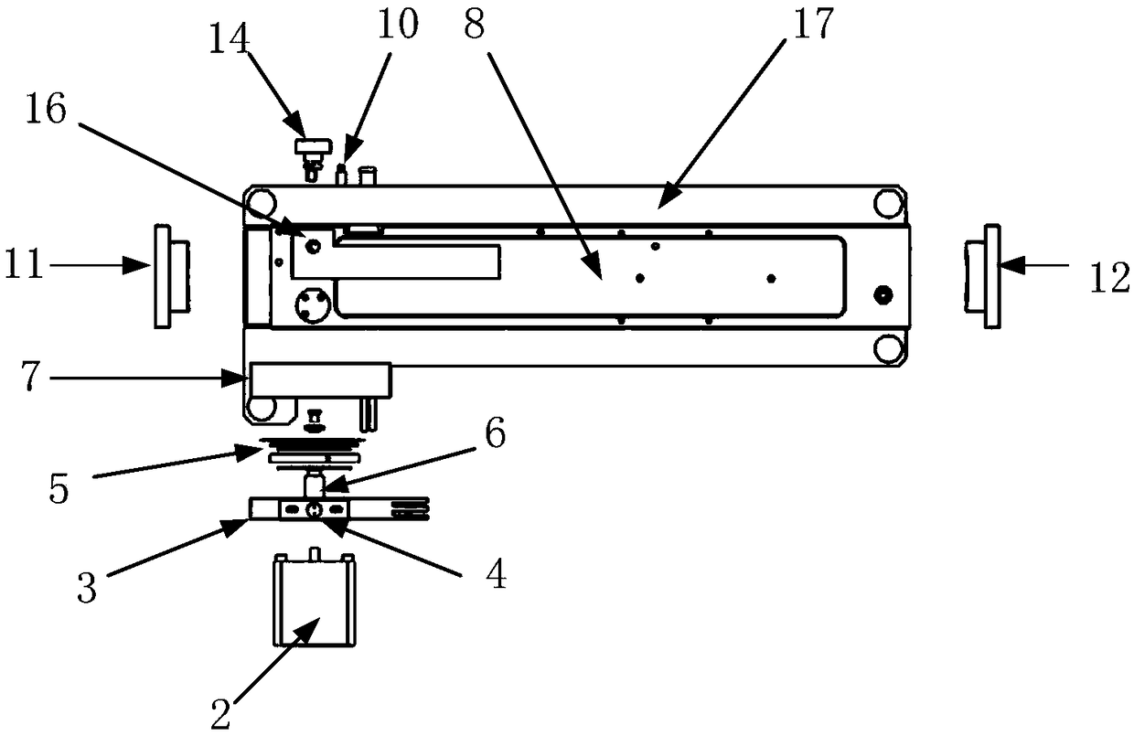
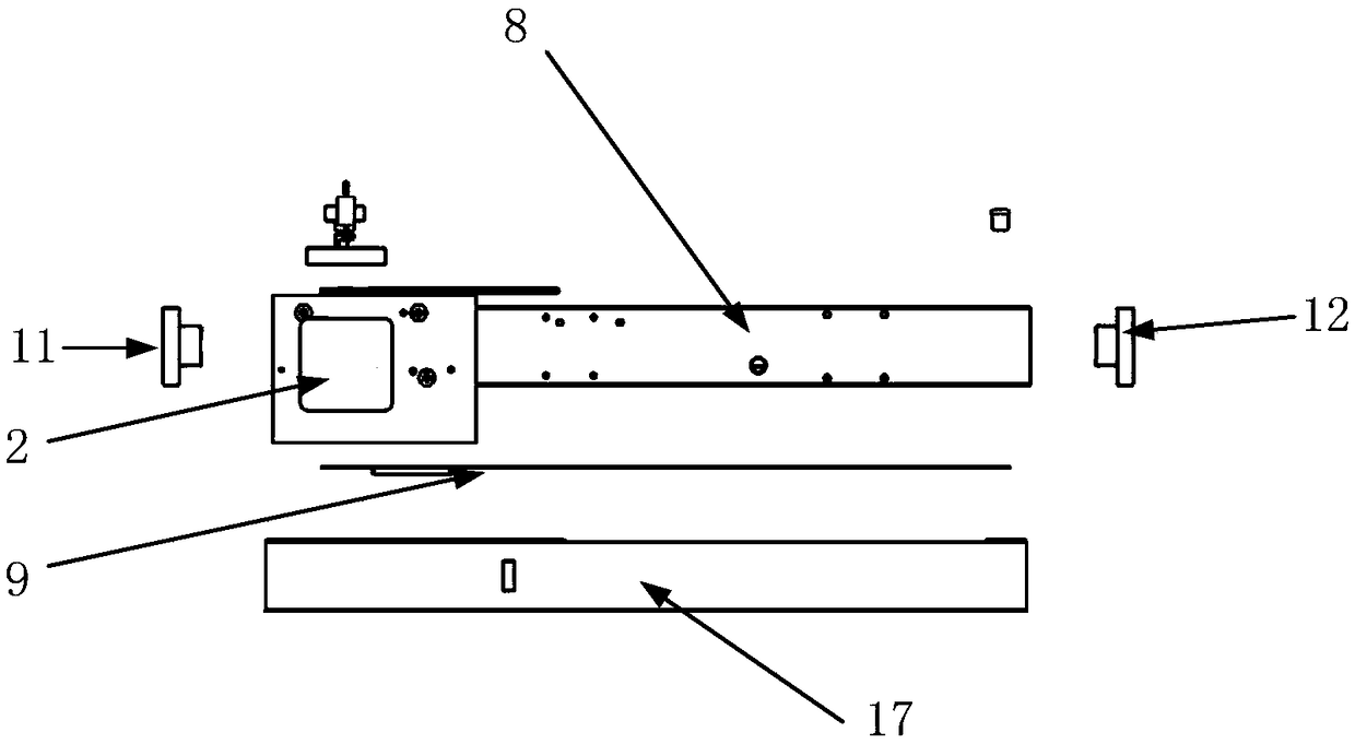
[0035] This embodiment provides a long optical path trace poisonous and harmful gas detection device, including: servo motor 2, connecting seat 3, infrared light source 4, inflatable optical rotation wheel 5, shaft sleeve 6, heat-insulated outer cavity seat 7, and pool body 8. Heating device 9, temperature sensor 10, primary reflector 11, secondary reflector 12, first reflector 13, second reflector 14, optical filter 15, infrared detector 16 and cell body support 17;

[0036] See attached Figure 5, the pool body 8 is made of stainless steel and is a rectangular shell with two opposite ends open. The six faces of the rectangular shell are respectively the upper side, the lower side, the front side, the rear side, the left open end face and the right open end face, And the processing parallelism error of the left opening end face and the right opening end ...


PUM

PropertyMeasurementUnit
power consumptionaaaaaaaaaa

Abstract

The invention discloses a long optical path trace toxic and harmful gas detecting device, and belongs to the technical field of infrared gas detection. The detecting device comprises an infrared source, an inflatable optical rotating wheel, a tank, a main mirror, a secondary mirror, a first mirror, a second mirror, an optical filter and an infrared detector; the infrared light emitted by the infrared source is irradiated on the inflatable optical rotating wheel to form an infrared modulated signal light, which enters the inner cavity of the tank; the first mirror is used for reflecting the infrared modulated signal light to a minor reflector; an optical path is repeatedly reflected between the primary mirror and the secondary mirror; the second mirror is used for emitting the infrared modulated signal light reflected by the minor reflector from a light outlet; and the infrared modulated signal light emitted from the minor reflector is irradiated on an infrared detector after passing the filter. According to the invention, a mono-component ppb level toxic and harmful gas can be measured and detected on line in real time by only replacing the filtering for testing different toxic andharmful gases and the optical rotating wheel for testing toxic and harmful high-purity sample gases.

Description

technical field [0001] The invention belongs to the technical field of infrared gas detection, and in particular relates to a long optical path trace poisonous and harmful gas detection device. Background technique [0002] With the increasing hazards of sudden pollution accidents, such as the 812 Tianjin explosion, natural disasters, terrorist incidents, and industrial pollutant emissions, the sudden discharge of toxic and harmful gases into the atmosphere has caused great harm to human life and safety. Therefore, online monitoring equipment for polluting gases has attracted more and more attention. At present, the monitoring technologies of polluted gases mainly include ionization method, electrochemical method, and infrared absorption spectroscopy. Among them, the ionization method mainly includes electric spark method, ion mobility spectrometry, etc., and the chemical method mainly includes thermal catalytic method, electrochemical method and gas chromatography, etc., b...

Claims


Application Information

Patent Timeline
Patent Type & Authority Applications(China)
IPC IPC(8): G01N21/3504G01N21/01
CPCG01N21/01G01N21/3518
Inventor 尤兴志隋峰兰江苏超魏东
Owner 中船重工安谱(湖北)仪器有限公司
Why Eureka
Try Eureka