Eureka AIR delivers breakthrough ideas for toughest innovation challenges, trusted by R&D personnel around the world.

A liquid level detection system and method for medical instruments

A liquid level detection and medical instrument technology, which is applied in the field of liquid level detection system of medical instruments, can solve the problems of low reliability, low anti-interference ability, poor scalability, etc., to prevent cut-off or saturation, reduce DC drift, Judging the effect of accurate results

Active Publication Date: 2019-11-22
宁波海尔施智造有限公司
View PDF13 Cites 0 Cited by
  • Summary
  • Abstract
  • Description
  • Claims
  • Application Information

AI Technical Summary

Problems solved by technology

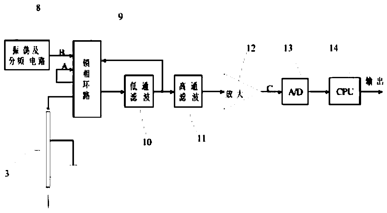
[0003] In the prior art, the commonly used liquid level detection adopts a capacitive liquid level detection circuit, such as figure 1 As shown, the circuit is composed of oscillation and frequency division circuit, phase-locked loop, low-pass filter, high-pass filter, amplification, AD conversion, CPU processing and other parts. figure 1 The method shown adopts the conventional probe capacitance detection method. Since it is not convenient to directly measure the probe capacitance and its variation in engineering, the circuit in the prior art usually converts the capacitance into a voltage, and then converts it through AD However, the above-mentioned circuit design costs are high, the adjustment is cumbersome, the reliability is low, the circuit structure is complex, and the scalability is poor. The voltage control in the phase-locked loop The oscillator adopts RC type, its anti-interference ability is low, so the detection accuracy is low

Method used


Image

  • A liquid level detection system and method for medical instruments
  • A liquid level detection system and method for medical instruments
  • A liquid level detection system and method for medical instruments

Examples


Embodiment 1

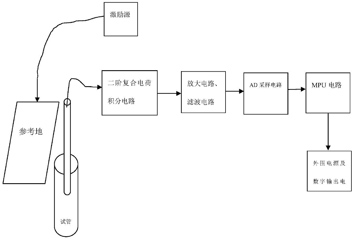
[0046] This embodiment provides a liquid level detection system used in medical instruments to solve the problem of insufficient accuracy of liquid level detection in the prior art, such as figure 2 As shown, the system includes:

[0047] The excitation source is used to provide a preset voltage signal to excite the sample needle to generate an induced charge;

[0048] The sample needle is used to absorb the measured liquid and output its own induced charge;

[0049] The acquisition circuit is connected with the sample needle, and is used to collect the induced charge output by the sample needle in real time and convert it into a corresponding analog signal of the induced charge;

[0050] The AD sampling circuit is used to convert the analog signal of the induced charge amount into a digital signal of the induced charge amount through an AD converter;

[0051] The MPU circuit is connected with the AD sampling circuit, which is used to compare the digital signal of the induc...

Embodiment 2

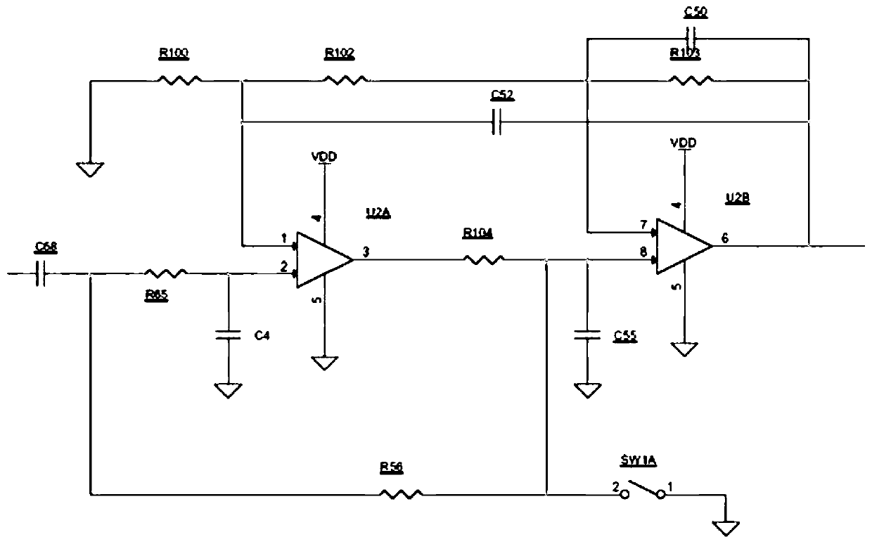
[0066] This embodiment provides a liquid level detection system for medical instruments to solve the problem of inaccurate inductive charges collected by the acquisition circuit in the liquid level detection circuit, such as image 3 Shown, this system compares embodiment one:

[0067] Further, the collection circuit is a second-order composite charge integration circuit, which is used to close the switch according to a preset time and then open it to collect the integrated charge of the sample needle in real time.

[0068] Further, the second-order composite charge integration circuit includes: resistor R56, resistor R65, resistor R100, resistor R102, resistor R103, resistor R104, capacitor C4, capacitor C50, capacitor C52, capacitor C55, capacitor C68, amplifier U2A, amplifier U2B, switch SW1A;

[0069] One end of the capacitor C68 is connected to the sample needle, the other end of the capacitor C68 is connected to one end of the resistor R65 and one end of the resistor 56...

Embodiment 3

[0072] In this embodiment, a liquid level detection method for medical instruments is provided, such as Figure 4 to Figure 5 As shown, this method includes:

[0073] S1: collect the analog signal of the induced charge generated by the sample needle due to the voltage provided by the excitation source through the acquisition circuit;

[0074] S2: converting the collected analog signal of induced charge into a digital signal of induced charge;

[0075] S3: Compare the digital signal of the induced charge with the preset non-contact digital signal, and judge whether the digital signal of the induced charge is within the range of the preset non-contact digital signal. If so, confirm that the current sample needle is not in contact with the liquid surface; if not , confirm that the current sample needle touches the liquid surface;

[0076] S4: Outputting the confirmation result, and displaying the confirmation result on the preset display interface.

[0077] Further, step S1 in...


PUM


Abstract

The invention provides a liquid level detection system for medical instruments, which is used to solve the problem of inaccurate sample needle sampling in the prior art, excessive sampling of unnecessary liquid by the sample needle, resulting in cross-contamination. The system includes: an excitation source, which excites the sample needle to generate an induced charge; a sample needle, which is used to absorb the measured liquid and output its own induced charge; an acquisition circuit, which collects the induced charge output by the sample needle in real time and converts it into a corresponding induced charge analog signal; AD sampling circuit, which converts the analog signal of the induced charge into a digital signal of the induced charge; MPU circuit, which is used to compare the digital signal of the induced charge with the preset non-contact digital signal, and confirm whether the sample needle is in contact with the liquid surface; digital output circuit for outputting confirmation results. The invention can accurately confirm that the sample needle touches the liquid surface, thereby controlling the liquid suction stroke of the sample needle and ensuring that the liquid sucked by the sample needle is the preset sampling liquid.

Description

technical field [0001] The invention relates to the field of medical equipment auxiliary equipment, in particular to a liquid level detection system and method of a medical equipment. Background technique [0002] When analyzing body fluids, automatic biochemical analyzers and immune analyzers in medical testing need to take samples first. During the sampling process, the liquid-absorbing sample needle is driven by the motor and goes down in the sample test tube. When it touches the liquid surface, in order to prevent Inserting the sample needle too deeply will increase the difficulty of cleaning. If the cleaning is not clean, it will cause cross-contamination, so the motor must be stopped. After the sample needle absorbs the body fluid, it will go up and return under the drive of the motor. The liquid level detection is carried out first, that is, when the sample needle touches the liquid level, it is necessary to output a contact liquid level signal to the motor to control...

Claims


Application Information

Patent Timeline
Patent Type & Authority Patents(China)
IPC IPC(8): G01F23/22
CPCG01F23/22
Inventor 柳建敏刘立辉曹宽宽徐睿何佳俊
Owner 宁波海尔施智造有限公司
Why Eureka
Eureka Blog
Learn More